Introduction
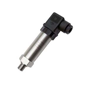
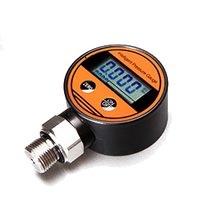
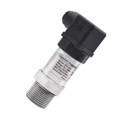
SPI Pressure Sensor (Serial Peripheral Interface) has become the gold standard for modern industrial applications requiring fast, accurate, and noise-immune pressure measurements.
Unlike analog output sensors that suffer from signal degradation over long cable runs, SPI pressure sensors transmit digital data directly from the sensing element, ensuring measurement integrity even in electrically noisy environments.
Whether you’re an engineer integrating a pressure sensor into your next design or a procurement professional seeking the best value for your organization, this comprehensive guide will help you navigate the technical specifications, integration challenges, and procurement considerations that matter most.
Why SPI Communication for Pressure Sensors?
The Digital Advantage
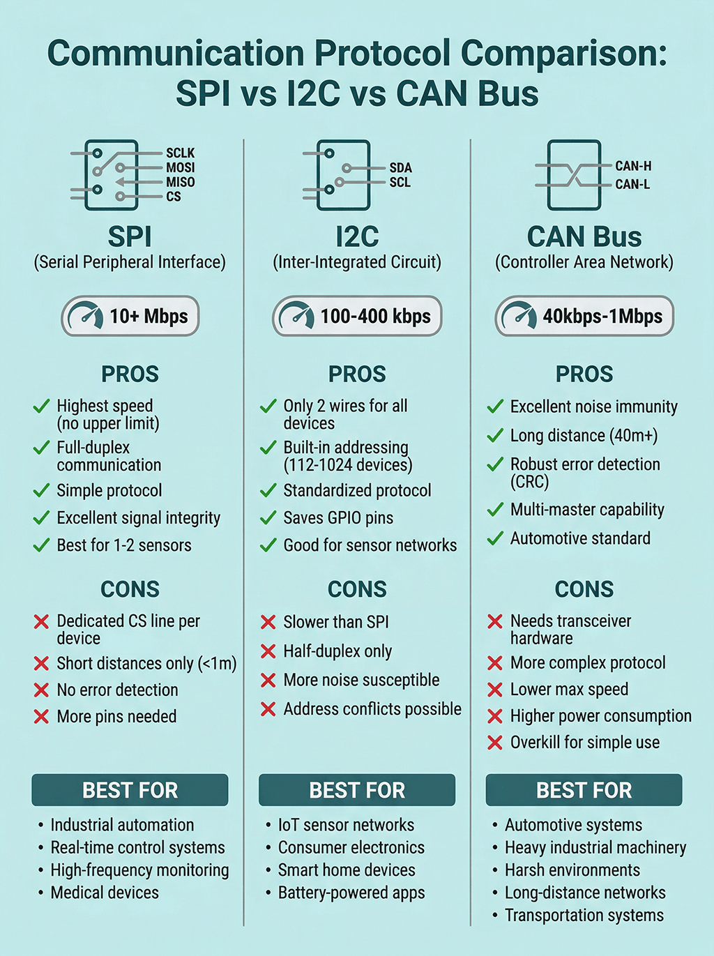
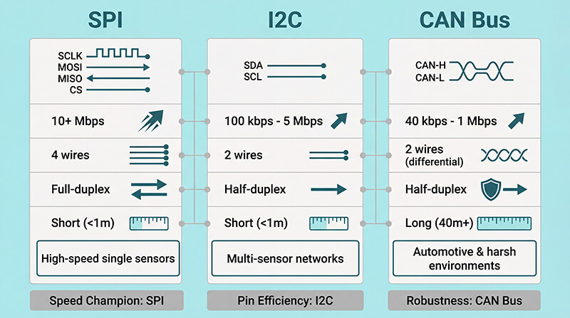
SPI communication offers several compelling advantages over traditional analog (0-5V, 4-20mA) and even I2C digital interfaces:
Speed and Performance
SPI operates at clock speeds from 1 MHz to over 10 MHz, enabling real-time pressure monitoring for fast-changing processes. This makes SPI ideal for applications like engine control systems, pneumatic automation, and dynamic pressure testing where response time is critical.
Noise Immunity
Digital signals are inherently resistant to electromagnetic interference (EMI). In industrial environments with motors, relays, and switching power supplies, SPI maintains signal integrity where analog sensors would produce erratic readings.
Cable Length Flexibility
While SPI itself is designed for short-distance communication (typically under 1 meter on the PCB), the digital nature allows for easy integration with differential line drivers or optical isolators to extend reliable communication over longer distances without signal degradation.
Click to find more details about: Pressure Sensor Cable
Multi-Sensor Systems
SPI’s chip-select architecture allows a single microcontroller to communicate with multiple pressure sensors (2 nos) on the same bus, simplifying system design for multi-point pressure monitoring.
Key Technical Specifications to Consider
Pressure Measurement Specifications
Pressure Range: Choose the smallest range that covers your maximum expected pressure plus 20-30% safety margin. Oversized ranges sacrifice resolution and accuracy.
Accuracy: Typically specified as ±0.5% to ±1% of full-scale output (FSO). For critical applications, look for sensors with accuracy better than ±0.25% FSO including temperature effects.
Temperature Compensation: Essential for real-world applications. Quality SPI pressure sensors incorporate onboard temperature compensation with coefficients stored in internal memory, delivering consistent accuracy across -40°C to +125°C operating ranges.
Media Compatibility: For direct media contact, verify chemical compatibility with your process fluid. Stainless steel diaphragms handle most gases and non-corrosive liquids, while specialized coatings or ceramic elements are required for aggressive chemicals.
SPI Configuration Parameters
Parameter Typical Range Selection Criteria
Clock Speed 1-10 MHz Match to MCU capability; higher speeds reduce read time
SPI Mode Mode 0 or Mode 3 Verify compatibility with your microcontroller
Data Format 16-24 bit Higher resolution provides better measurement precision
Chip Select Logic Active Low/High Must match MCU GPIO configuration
Update Rate 100-10,000 Hz Select based on application dynamic requirements
Communication Protocol Comparison: SPI vs I2C vs CAN Bus
Choosing the right communication protocol is critical for system performance, your decision to use which protocol between SPI, I²C, and CAN Bus will influence the entire system design—from PCB layout to firmware complexity to scalability
We summarize the detailed comparison of the three most common digital interfaces for pressure sensors:
Integration Guide for Engineers
Hardware Connection Best Practices
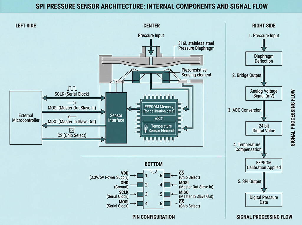
The typical SPI pressure sensor requires four signal lines plus power:
- SCLK (Serial Clock): Driven by the master (microcontroller)
- MOSI (Master Out Slave In): Command/configuration data to sensor
- MISO (Master In Slave Out): Pressure data from sensor
- CS (Chip Select): Activates the specific sensor
- VDD/GND: Power supply (typically 3.3V or 5V)
Critical Design Considerations:
- PCB Layout: Keep SPI traces short and direct. Use ground planes to minimize crosstalk. Place decoupling capacitors (0.1µF ceramic + 10µF tantalum) within 5mm of the sensor’s power pins.
- Pull-up/Pull-down Resistors: Some sensors require external pull-up resistors on MISO line (typically 4.7kΩ to 10kΩ). Always consult the datasheet.
- ESD Protection: Pressure sensors exposed to harsh environments benefit from TVS diodes on signal lines, especially if connectors are involved.
- Voltage Level Compatibility: Ensure logic level compatibility between your microcontroller and sensor. Use level shifters if mixing 3.3V and 5V systems.
Software Implementation Essentials
Initialization Sequence: Most SPI pressure sensors require a specific startup sequence:
- Apply power and wait for sensor stabilization (typically 5-50ms)
- Send configuration commands to set measurement mode and resolution
- Read calibration coefficients if stored externally
- Begin periodic pressure readings
Reading Pressure Data: A typical read operation involves:
- Assert CS low
- Send read command byte
- Clock in pressure data (16-24 bits)
- Deassert CS high
- Convert raw counts to engineering units using calibration data
Error Handling: Implement these safeguards in your firmware:
- Check for communication timeouts (sensor failure or disconnection)
- Validate data range (detect out-of-range readings indicating sensor fault)
- Monitor sensor status bits if available (saturation, temperature error flags)
- Implement watchdog reset if sensor stops responding
Conversion and Scaling: The raw digital output requires conversion to pressure units. The typical formula is:
Pressure = (Digital_Counts – Offset) × Span / Full_Scale_Counts
Calibration coefficients (Offset and Span) are either stored in sensor non-volatile memory or must be programmed during manufacturing.
Common Integration Challenges and Solutions
Challenge Symptoms Solution
No sensor response All readings zero or 0xFF Verify power supply, check CS polarity, confirm SPI mode settings
Erratic readings Random fluctuating values Add decoupling capacitors, reduce clock speed, check for EMI sources
Fixed reading Value doesn't change with pressure Verify sensor is not saturated, check pressure port not blocked
Communication errors CRC failures, framing errors Reduce cable length, add series termination resistors, lower clock speed
Temperature drift Readings shift with ambient temperature Enable internal temperature compensation, verify compensation algorithm
Procurement Guide
Before requesting quotes, if you can create a clear specification document including the following, it will definitely help you to find the most proper SPI Pressure sensor.
Environmental Requirements:
- Operating pressure range and proof pressure (typically 2× operating range)
- Operating temperature range
- Media exposure (gas, liquid, chemical composition)
- Humidity and condensation exposure
- Vibration and shock levels (specify in G forces)
Electrical Requirements:
- Supply voltage and current consumption
- SPI clock speed and mode
- Output data format and resolution
- Update rate requirements
Mechanical Requirements:
- Pressure port type (threaded, barbed, manifold mount)
- Port size and thread standard (1/4″ NPT, M5, G1/8, etc.)
- Electrical connector type or cable requirements
- Mounting method and orientation sensitivity
Calibration and Testing: Reputable manufacturers perform multi-point pressure calibration across the full operating temperature range. Request calibration certificates and ask about traceability to national standards (NIST, PTB, etc.).
Long-term Stability: Quality sensors maintain accuracy over time. Look for specifications on annual drift (typically <0.1% FSO per year for quality sensors).
Technical Support: Manufacturers offering comprehensive datasheets, application notes, reference firmware code, and responsive technical support deliver better long-term value than the cheapest price alone.
Cost Optimization Strategies
Volume Considerations: Unit prices typically decrease significantly at volumes above 500, 2000, and 10000 pieces. If designing for production, negotiate pricing tiers in advance.
Customization vs. Standard: Standard catalog sensors offer faster delivery and lower NRE (non-recurring engineering) costs. Custom sensors allow optimization for your specific requirements but require tooling costs and longer lead times (typically 8-12 weeks for first articles).
Red Flags to Avoid
Be cautious of suppliers who:
- Cannot provide detailed datasheets with actual test data
- Offer prices significantly below market (often indicates substandard components)
- Cannot explain their calibration process or provide traceability
- Have minimum order quantities that seem arbitrary or excessive for standard products
- Cannot provide samples for evaluation before production orders
- Lack technical staff who understand SPI communication protocols
Application Examples and Use Cases
Industrial Automation and Process Control
SPI pressure sensors excel in industrial automation applications requiring fast response times and high reliability. In pneumatic control systems, SPI sensors monitor cylinder pressures and valve states with update rates exceeding 1 kHz, enabling precise closed-loop control. The digital output eliminates noise pickup from motor drives and variable frequency drives (VFDs) that plague analog sensors in industrial environments.
Medical Devices and Healthcare
Medical applications demand exceptional accuracy, repeatability, and biocompatibility. SPI pressure sensors are used in ventilators for monitoring airway pressure, in infusion pumps for detecting occlusions, and in blood pressure monitors for non-invasive measurements. The digital interface simplifies integration with medical device microcontrollers while providing the diagnostic capabilities required for safety-critical systems.
Automotive and Transportation
Modern vehicles contain dozens of pressure sensors monitoring engine oil pressure, tire pressure (TPMS), brake systems, and HVAC systems. SPI and CAN Bus pressure sensors with AEC-Q100 qualification withstand the harsh automotive environment including extreme temperatures (-40°C to 125°C), vibration, and humidity.
The digital output integrates seamlessly with automotive microcontrollers and CAN bus systems.
IoT and Smart Buildings
Battery-powered IoT devices benefit from SPI pressure sensors with ultra-low power sleep modes. Smart building applications use barometric pressure sensors for floor-level detection in elevators, HVAC optimization, and weather monitoring. Low power consumption (0.5 µA in standby) and small package sizes make SPI sensors ideal for distributed IoT sensor networks.
FAQ: SPI pressure sensor
1. What's the maximum cable length for SPI pressure sensors?
Standard SPI works reliably under 1 meter. For longer distances (up to 10 meters), use differential line drivers, twisted-pair shielding, or reduce clock speed below 1 MHz to maintain signal integrity.
2. Can I connect multiple SPI pressure sensors to one microcontroller?
Yes. Use individual chip select (CS) lines for each sensor while sharing SCLK, MOSI, and MISO lines.
Ensure sensors have tri-state MISO outputs to prevent bus contention issues.
3. What's the typical power consumption of SPI pressure sensors?
- Active measurement mode: 1-5 mA at 3.3V or 5V.
- Sleep mode: 1-50 µA.
Total consumption depends on sampling rate and active time percentage in your application.
4. How do I verify my SPI pressure sensor is working correctly?
Check power supply voltage, measure SPI signals with oscilloscope, verify CS and clock polarity, read sensor ID register, apply known pressure, and compare readings against reference gauge.
5. What causes unstable or noisy pressure readings from SPI sensors?
Common causes include inadequate power supply decoupling, EMI from nearby switching circuits, incorrect SPI mode configuration, excessive clock speed, poor PCB grounding, or actual pressure fluctuations in your system.
6. Do SPI pressure sensors require external calibration after installation?
Quality SPI pressure sensors include factory calibration data in internal memory, requiring no field calibration.
However, system-level verification against reference standards ensures measurement accuracy for critical applications.
7. What's the difference between SPI Mode 0 and Mode 3 for pressure sensors?
- Mode 0: Clock idles low, data captured on rising edge.
- Mode 3: Clock idles high, data captured on rising edge.
Both work; verify sensor datasheet and configure microcontroller accordingly.
8. How do I select between 3.3V and 5V SPI pressure sensors?
Match your microcontroller voltage to avoid level shifters.
- 3.3V sensors consume less power (ideal for battery applications).
- 5V sensors offer better noise immunity in industrial environments with electrical interference.
9. What's typical lead time for custom SPI pressure sensor orders?
Standard catalog sensors: 2-4 weeks. Custom pressure ranges or mechanical configurations: 8-12 weeks including first article approval. Tooling for unique designs adds 4-6 weeks. Request samples early for testing.
For details, please CONTACT US, our engineer will get back to you at the fist time.
10. Can SPI pressure sensors measure vacuum and positive pressure?
Yes. Specify sensors as absolute (measures vs. vacuum), gauge (measures vs. atmospheric), or compound/bidirectional ranges (e.g., -15 to +30 PSI) based on your application requirements and reference point.
Conclusion
Selecting and integrating SPI pressure sensors requires balancing technical performance, cost, and reliability. By understanding the communication protocol fundamentals, carefully specifying your requirements, and choosing manufacturing partners with demonstrated quality, you can develop robust pressure measurement systems that deliver years of reliable service.
For engineers, focus on proper hardware design, robust firmware implementation, and thorough testing across your operating envelope.
For procurement professionals, look beyond unit price to total cost of ownership, supplier capabilities, and long-term supply chain reliability.
With the right sensor properly integrated, SPI pressure measurement provides the accuracy, speed, and reliability demanded by today’s advanced industrial, medical, and automotive applications.