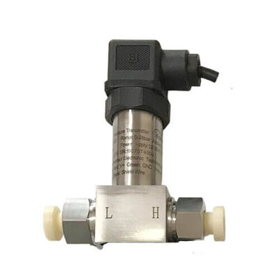
The Role of 4-20mA Pressure Sensor
Current output signals in pressure sensing refer to the method by which a sensor communicates the pressure it’s measuring to other devices. The most common type of current output is 4-20mA Pressure Sensor, a current loop standard in many industries.
4-20mA Current Loop
The 4-20mA current output works on the principle that the current running through the loop is proportional to the pressure being measured by the sensor.
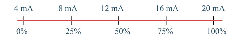
For a given pressure range,
- 4mA represents the lowest pressure
- 20mA represents the highest
For example,
A pressure sensor with a range of 0-100 psi (pounds per square inch) outputs 4mA of current at 0 psi and 20mA at 100 psi.
If the sensor is measuring a pressure of 50 psi, halfway between 0 and 100, the output would be 12mA, halfway between 4 and 20mA.
Understanding 4-20mA Current Loop Output Signals in Pressure Sensors
Current output signals, particularly the widespread 4-20mA standard, play a crucial role in pressure sensing. They offer a robust and reliable method of conveying pressure information from the sensing location to a remote reading or control device.
What 4-20mA Pressure Sensor can do?
- Can be used for hundreds or even thousands of meters long distances
- Can be installed in environments with high electrical noise
- Can easily detect the fault
- Give proportional representation of the pressure
- Have wide compatibility and easy integration
1. Data Transmission Over Long Distances
Current output signals can be transmitted over long distances without signal degradation. This is in contrast to voltage signals, which can degrade over long cable runs.
For example, a sensor installed in an industrial plant can send accurate readings to a control room located hundreds of meters away.
Current output signals maintain their integrity over long distances.
The reason for this is that in a 4-20mA current loop, the current is regulated to remain constant across the entire loop, regardless of any changes in resistance along the loop (for example, due to increased cable length or changes in temperature).
This means that a 4-20mA current signal can be reliably transmitted over hundreds, or even thousands, of meters without significant loss of signal quality.
This makes current output signals particularly beneficial in large industrial facilities where the sensor and the monitoring or control equipment may be far apart.
Voltage signals are also more susceptible to interference from external electrical noise, which can additionally degrade the signal over long distances.
For short distances, such as in smaller machinery or consumer electronics, voltage output can be perfectly adequate. However, for longer distances, current output is generally the superior choice due to its greater signal integrity and noise immunity.
2. Noise Immunity
Electrical noise, common in industrial environments, can interfere with signal transmission.
Current output signals are less susceptible to such noise compared to voltage signals. This ensures that the pressure information is accurately conveyed, even in electrically noisy environments.
The primary reason that current signals are less affected by electrical noise compared to voltage signals lies in the very nature of these signals:
2.1 Consistency of Current:
In a 4-20mA current loop, the current is kept constant across the entire loop at any given time. This means that any induced noise would need to significantly alter the current level to affect the signal. This is much harder to achieve than altering a voltage level due to the physical properties of electric currents.
2.2 Voltage Drops and Noise:
Voltage signals are more susceptible to noise because they can be influenced by voltage drops across the line due to resistance, particularly in long cable runs. This is not an issue with current signals, as the current remains constant across the loop, regardless of line resistance.
2.3 Ground Potential Differences:
Voltage signals can be affected by differences in ground potential between different points in the system, which can introduce noise.
Current signals are largely unaffected by this issue.
In practical terms, this means that a pressure sensor using a 4-20mA current output signal can be used in environments with high electrical noise without the fear of the signal being distorted before it reaches the control system or display.
3. Easy Fault Detection
The 4-20mA current range is designed to facilitate fault detection.
A signal below 4mA or above 20mA, or a complete drop to 0mA, indicates a problem.
In a 4-20mA system, the “live zero” at 4mA is a key to fault detection:
3.1 Circuit Integrity:
If the current ever drops to 0mA, it typically indicates a break in the circuit, such as a severed wire or disconnection.
In a voltage signal system, a 0 voltage could either mean a circuit break or a zero measurement, making it harder to distinguish between the two. But in a 4-20mA system, 0mA can only mean a fault in the loop.
3.2 Sensor or Device Failure:
Any current reading below 4mA or above 20mA is also considered a fault condition. If the current falls below 4mA, it could suggest an issue with the sensor or other equipment in the loop, such as power supply problems. If the current goes beyond 20mA, it could indicate an over-range condition or a sensor malfunction.
3.3 Communication Errors:
Variations in the signal that are not consistent with the behavior of the system (for example, erratic fluctuations) could indicate a communication problem, such as noise interference or signal reflection. These can be identified and diagnosed by monitoring the 4-20mA signal.
So, the 4-20mA standard provides a clear ‘window’ for normal operation, and any readings outside of that window inherently indicate a fault, making troubleshooting more straightforward.
This capability is one of the key reasons why the 4-20mA standard is widely used in industrial control systems.
4. Proportional Representation
A key aspect of the proportional representation is that it’s a linear relationship.
This means every increment in pressure corresponds to an equally spaced increment in current. This linear relationship simplifies the interpretation of sensor data, as the output can be easily scaled to the input pressure.
For example
Consider a typical pressure sensor with a 4-20mA current loop output.
The sensor’s pressure range might be from 0 to 100 psi (pounds per square inch).
In this scenario,
- 0 psi corresponds to 4mA output,
- 100 psi corresponds to 20mA output.
This setup implies that the current output is directly proportional to the pressure sensed.
To understand this further, consider a pressure of 50 psi, which is halfway between 0 and 100 psi. The corresponding current would be halfway between 4mA and 20mA, which is 12mA.
Similarly, a pressure of 58 psi, a quarter more of the way from 0 to 100 psi, would correspond to a current a quarter of the way from 4mA to 20mA.
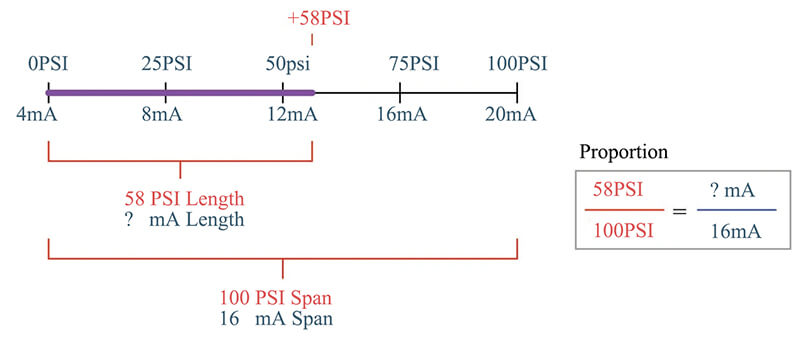
In mathematical terms, this proportionality can be expressed as:
Current Output = 4mA + [(Measured Pressure / Full Scale Pressure Range) * 16mA]
Using this equation with a pressure of 58 psi in a 0-100 psi sensor gives:
Current Output = 4mA + [(58psi / 100psi) * 16mA] = 13.28mA
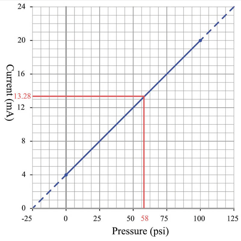
This shows how the current output from the sensor is a proportional representation of the pressure: as the pressure changes, the current changes proportionally. This proportionality allows the pressure to be accurately measured and monitored over the 4-20mA current loop.
5. Compatibility and Integration
The 4-20mA standard’s wide acceptance and compatibility make it a versatile choice for pressure sensing applications in a variety of industries. Its ease of integration and strong signal integrity over long distances add to its advantages.
5.1 Compatibility
The 4-20mA standard is recognized and understood globally, and as such, it’s easy to find compatible equipment. Many types of industrial control systems, Programmable Logic Controllers (PLCs), and Human Machine Interfaces (HMIs) readily accept 4-20mA signals. This compatibility extends to a wide variety of industries, including manufacturing, oil and gas, water treatment, and more.
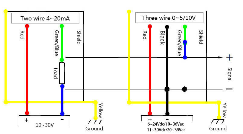
5.2 Integration
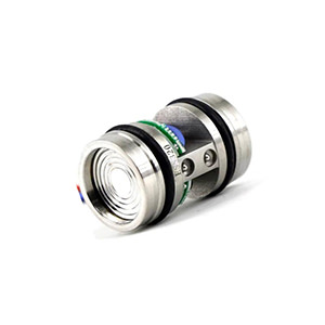
Integrating a 4-20mA pressure sensor into a system is relatively straightforward due to the prevalence of this standard. The sensor will typically need a power supply, which is often 24 volts DC, although the exact requirements can vary.
The sensor’s current output can be directly connected to the input of the control system or display device. If the device is designed to accept 4-20mA signals, no further signal conditioning should be required. This simplicity makes integrating 4-20mA sensors into a system relatively easy.
However, it’s important to ensure the sensor is correctly calibrated for the pressure range it’s intended to measure. This usually involves applying known pressures to the sensor and adjusting its output to align with these pressures.
Additionally, some advanced systems allow for digital communication over the 4-20mA loop, such as HART (Highway Addressable Remote Transducer) protocol. This can allow for bidirectional communication with the sensor for configuration or diagnostics, although this requires compatible equipment and adds complexity to the system.
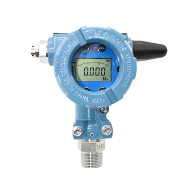
Click to check details: 4-20mA Pressure Transmitter
Why is it must be 4mA instead of 3mA or 2mA and 1mA?
The choice of 4mA as the lower limit for current loop standards, like the 4-20mA used in pressure sensors and other industrial devices, was a carefully considered decision and it serves several purposes.
In essence, the 4mA lower limit is a balance between providing enough power for the sensor, allowing for fault detection, improving noise immunity, and maintaining compatibility with existing systems and practices.
1. Fault Detection
The primary reason for choosing 4mA as the lower limit is for fault detection.
As we previously mentioned, if the current ever falls to 0mA, it’s an indication of a fault condition, such as a break in the loop or a power failure. If the lower limit were set at 0mA, 1mA, 2mA, or 3mA, it would be more difficult to distinguish between a legitimate low reading and a fault condition.
2. Power Supply to the Sensor:
Many 4-20mA devices are 2-wire devices, meaning they derive their power from the current loop itself.
The 4mA lower limit provides enough power for these devices to operate correctly, even when the sensor reading is at its lowest.
A lower baseline current might not provide enough power for the sensor to function properly.
3. Noise Immunity:
Electrical noise is a common issue in industrial environments.
Having a baseline of 4mA instead of a lower value helps the signal stand out above the noise, improving the signal-to-noise ratio and ensuring more reliable communication.
4. Standardization and Compatibility
The 4-20mA standard is widely recognized and accepted in many industries.
This ensures compatibility with a wide variety of equipment and systems. A different baseline current would require a shift in equipment and practices.
Why is it must be 20mA instead of 19mA or 21mA?
The choice of 20mA as the upper limit of the 4-20mA standard is largely based on a balance of practicality and historical convention.
The 20mA upper limit is a compromise between safety, power consumption, signal resolution, and compatibility considerations. It ensures that the current levels remain safe and power-efficient, while still providing enough signal resolution for most applications and maintaining compatibility with standardized equipment and systems.
1. Safety
One major factor is safety.
Currents above 20mA could potentially be harmful in certain conditions, especially in the presence of moisture. By setting the upper limit at 20mA, the standard ensures that the current levels remain within a safe range.
2. Power Consumption
Another consideration is power consumption. The higher the current, the more power is consumed. This becomes particularly important when the sensors are battery-powered or when the system includes many sensors. An upper limit of 20mA provides a good balance between signal resolution and power consumption.
3. Signal Resolution
With a 16mA range (from 4mA to 20mA), it’s possible to get a good signal resolution for most applications. If the upper limit was 19mA or 21mA, the range would be slightly smaller or larger, but the impact on signal resolution would be minimal.
4. Standardization and Compatibility
Above benefits make 4-20mA a widely accepted and recognized current loop standard across industries. A different upper limit would deviate from the standard and could potentially cause compatibility issues with existing equipment and systems.
What are other current loop standards
The 4-20mA current loop is the most widely used current loop standard for industrial pressure sensor applications. However, there are other current loop standards used in different contexts.
Let’s compare the 4-20mA standard to a few of these:
1. 0-20mA Standard
This is another current loop standard, but unlike the 4-20mA standard, it doesn’t provide a baseline current for fault detection. This means that if the current falls to zero, it could either indicate a zero measurement or a fault in the system, making it difficult to distinguish between the two.
2. 10-50mA Standard
Although less common today, the 10-50mA standard was used in older telecommunication systems. The higher current levels made it more suitable for long-distance transmission over copper wires with high resistance.
However, it’s less safe and less energy-efficient than the 4-20mA standard, particularly in hazardous environments.
3. 20mA Loop Standard
Some telegraph systems used a simple on-off current loop standard with a single 20mA current level. The presence or absence of the 20mA current represented a binary signal. This is a very different application from analog sensor data transmission and isn’t directly comparable to the 4-20mA standard.
4. Digital Current Loop Standards
In addition to these analog current loop standards, there are also digital current loop standards, such as the HART protocol. The HART protocol can be superimposed on a 4-20mA signal, allowing digital data to be transmitted along with the analog signal. This can be used for transmitting additional information, such as diagnostic data, from a smart pressure sensor.
In comparison to these other standards, the 4-20mA standard strikes a good balance between safety, energy efficiency, transmission distance, and fault detection capability. Its lower current levels are safer and more energy-efficient for most applications, while still being capable of transmission over long distances. The 4mA baseline current allows for effective fault detection and powers 2-wire devices. These benefits, along with its widespread acceptance, make the 4-20mA standard the preferred choice for many industrial sensor applications.
Drawbacks of current output signal 4-20mA?
While current output signals, particularly the 4-20mA standard, have many advantages that make them suitable for a variety of applications, they also come with a few limitations:
1.Power Consumption:
Current output signals require a certain amount of power to maintain the current loop. In battery-powered or energy-constrained systems, this could lead to faster depletion of power resources compared to voltage output signals.
2. Complexity and Cost:
The transmitters and receivers compatible with 4-20mA current loops can be more complex and expensive compared to those used with voltage signals. This can lead to higher overall system costs.
3. Limited to Single Sensor per Loop:
Each 4-20mA current loop typically represents the output from a single sensor. If you need to monitor multiple sensors, you’ll need multiple loops, which can add to the system’s complexity and cost.
4. Slow Response Times:
While 4-20mA loops are robust and reliable, they can sometimes have slower response times compared to voltage signals, which can limit their use in applications where rapid response to changes is required.
5. Lack of Bidirectionality:
Traditional 4-20mA systems are unidirectional, meaning they only transmit data in one direction – from the sensor to the control system. They don’t inherently support bidirectional communication, which would allow for things like remote sensor configuration or diagnostics.
Application that 4-20mA current loop pressure sensor can be used for
Current output pressure sensors, particularly those using the 4-20mA standard, find wide use in various industrial and commercial applications due to their robustness, reliability, and the ability to transmit signals over long distances without degradation.
1. Industrial Process Control:
Current output pressure sensors are used to monitor and control processes in industries such as chemical, petrochemical, and power generation. These processes often involve high pressures and temperatures, and the sensors help maintain safe operating conditions.
2. Oil and Gas:
In oil and gas applications, pressure sensors are used for well monitoring, drilling operations, and pipeline management. The 4-20mA standard allows the signals from these sensors to be reliably transmitted over long distances.
3. Aerospace:
Pressure sensors are critical in aircraft systems for altitude determination, engine pressure regulation, and hydraulic system monitoring.
In each of above applications, the key advantage of current output pressure sensors is their ability to provide accurate, reliable measurements even in challenging conditions and over long distances.
The 4-20mA standard used by these pressure sensors also allows for simple and effective fault detection and powers 2-wire devices.
What is more, pressure sensors with 4-20mA current loop output standard, are particularly well suited for use in hazardous areas and intrinsically safe applications.