
Seawater Destroys Standard Sensors in Months. Here's How to Make Yours Last a Decade.
A ceramic capacitive solution built around an Endress+Hauser sensing core — 0.1% FS accuracy, 200-meter reach, RS485 digital output.
Core Applications
- Offshore tide monitoring
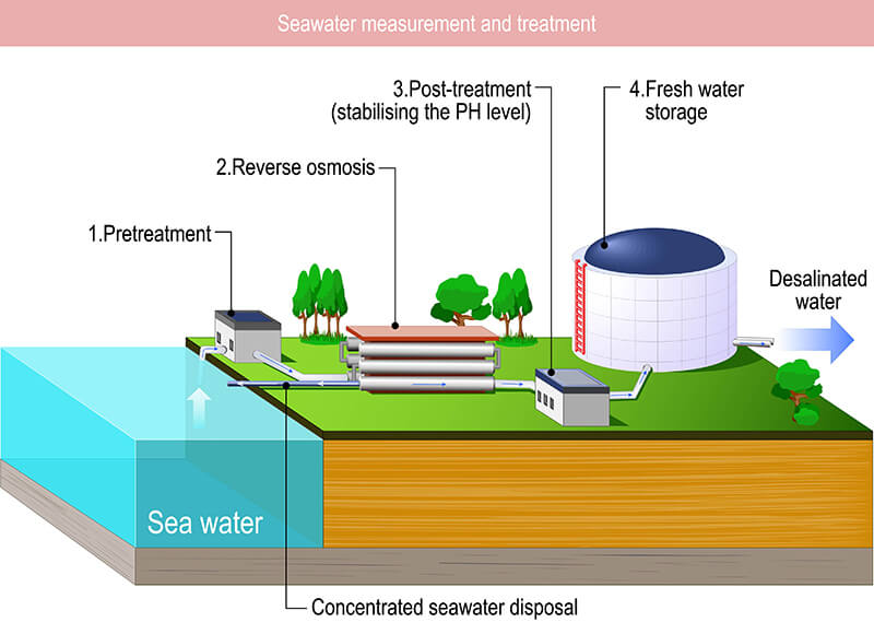
- Desalination plants
- Marine research stations
- Tank level control
- Coastal engineering
Key Parameters
- 0.1% FS accuracy
- 200m cable reach
- RS485 / Modbus RTU output
- SS316L housing
- Ceramic capacitive sensing
- IP68 rated
Proven Results
- 10+ year service life
- 50–70% cost savings
- E+H certified sensing core
- Maintenance interval: annual
The 30-Second Takeaway
⚡ The Bottom Line
Seawater is NOT just salty water — it's a corrosive, biofouling, thermally-cycling nightmare that eats standard sensors alive. The solution? A ceramic capacitive sensor with an Endress+Hauser core, SS316L housing, and RS485 digital output. This configuration delivers lab-grade accuracy in the harshest marine environments at 50–70% less than equivalent tier-one products.This guide walks through every critical decision point: why standard sensors fail, how ceramic capacitive technology overcomes marine challenges, why E+H sensing cores set the benchmark, and how to specify, install, and maintain a system that will still be delivering accurate data a decade from now.
Introduction
Seawater Level Measurement accurately presents unique challenges that go far beyond typical industrial level measurement applications. The combination of
Corrosive saltwater
Biofouling
Temperature variations
Remote installation locations
demands careful sensor selection…
After extensive research and comparison of available technologies,we’ve ultimately selected a ceramic capacitive sensing solution using an Endress+Hauser (E+H) core, fabricated with SS316 housing, featuring a 200-meter cable, 0.1% full-scale accuracy, and RS485 output.
This article documents my evaluation process and explains why this specific configuration emerged as the optimal solution for seawater level measurement.
Why Seawater Destroys Standard Sensors
The marine environment presents a unique combination of challenges that no single standard industrial sensor is designed to handle. Understanding these failure modes is the first step to specifying the right solution.
Corrosion
Chloride-rich seawater attacks most metals through galvanic and pitting corrosion. Standard stainless steels fail in months. Even 304 SS, common in industrial sensors, offers inadequate resistance to marine chloride concentrations.
Biofouling
Marine organisms coat sensor diaphragms within weeks, causing measurement drift or complete blockage. Barnacles, algae, and biofilm form rapidly in nutrient-rich coastal waters, creating both mechanical and chemical attack vectors.
Temperature Variation
From near-freezing to 30°C+, thermal expansion stresses sensors and affects calibration. Oil-filled isolation systems are particularly vulnerable — fill fluid viscosity and volume changes introduce systematic measurement errors.
Offshore Maintenance
Remote installations make maintenance painfully expensive. Every service call means vessel mobilization, diver deployment, or ROV operations. A sensor that needs quarterly replacement is not a sensor — it's a liability.
Understanding the Challenge: Why Seawater is Different
Seawater isn’t just water with salt; it’s a complex, aggressive medium that tests the limits of sensing technology.
The corrosive nature of seawater stems from its chloride content, which attacks most metals through electrochemical processes. Standard stainless steels that work perfectly well in freshwater or mild industrial environments can fail within months when exposed to seawater.
The salt concentration, typically around 3.5% but varying by location, combined with dissolved oxygen, creates an environment that promotes galvanic corrosion, pitting, and crevice corrosion.
Beyond corrosion, biofouling presents another significant challenge. Marine organisms including bacteria, algae, barnacles, and other creatures naturally colonize any submerged surface. This biological growth can coat sensor diaphragms, blocking pressure ports and causing measurement drift or complete failure. The rate of biofouling varies with water temperature, nutrient levels, and local marine life, but it’s an inevitable concern in any long-term seawater installation.
Temperature variations in marine environments also affect measurement accuracy. Seawater temperatures can range from near-freezing in polar regions to over 30°C in tropical areas, with seasonal and depth-related variations. Any pressure sensor must maintain accuracy across this temperature range while its materials withstand thermal cycling without degradation.
Finally, many seawater measurement applications involve remote or offshore installations where maintenance access is difficult and expensive. This reality places a premium on sensor reliability and long-term stability. A sensor failure isn’t just an inconvenience; it can mean costly vessel mobilization, diver operations, or platform shutdowns.
The Numbers That Matter
Initial Requirements Definition
The application required measuring seawater levels with 0.1% full-scale accuracy in a marine environment. The sensor needed to survive continuous immersion in seawater, maintain calibration over extended periods, and communicate reliably over a 200-meter distance to shore-based monitoring equipment. These requirements immediately narrowed the field of potential solutions and set the framework for evaluation process.
The accuracy requirement of 0.1% FS is demanding but not unprecedented in marine applications. For a 10-meter measurement range, this translates to ±10mm accuracy, accounting for all error sources including non-linearity, hysteresis, repeatability, and temperature effects.
This level of precision is necessary for applications such as
- Tide monitoring,
- Precise tank level control,
- Research measurements
where small variations matter…
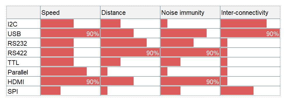
The 200-meter cable requirement arose from the physical layout of my installation site, where the measurement point is located offshore while monitoring and control systems are shore-based. This distance rules out most of the simple analog transmission and demands consideration of signal integrity, cable construction, and communication protocols capable of reliable long-distance operation in a electrically noisy marine environment.
Silicon Piezoresistive vs Ceramic Sensing
The fundamental choice in marine pressure sensing comes down to the sensing principle. Here's why ceramic capacitive wins in seawater environments — across every critical performance dimension.
| Feature | Silicon Piezoresistive | Ceramic Capacitive |
|---|---|---|
| Corrosion Resistance | ❌ Requires oil-filled isolation diaphragm | ✅ Inherently corrosion-proof alumina ceramic |
| Long-Term Stability | ⚠️ Oil degradation, diaphragm fatigue risk | ✅ No fill fluid; no drift mechanisms |
| Temperature Performance | ⚠️ Fill fluid expansion causes errors | ✅ Superior; less compensation needed |
| EMI Immunity | ⚠️ Susceptible to electrical noise | ✅ Capacitive principle naturally noise-resistant |
| Seawater Track Record | ⚠️ Limited; isolation failures common | ✅ Proven in offshore O&G, desalination |
| Cost | 💲 Lower initial | 💲💲 Higher initial, lower lifecycle |
| 🏆 VERDICT: Ceramic capacitive eliminates the failure modes that make silicon piezoresistive unreliable in seawater. | ||
«It's not the sensing chip that fails — it's what actually touches the seawater.»
— Core principle of marine sensor engineering
The Silicon Sensor Failure Path
Understanding why silicon piezoresistive sensors fail in marine environments requires examining the complete signal path from seawater to sensing element. Every interface is a potential failure point.
Technology Comparison: Silicon Piezoresistive vs. Ceramic Solutions
The evaluation began with understanding the fundamental sensing technologies available for pressure and level measurement.
The two primary technologies considered were silicon piezoresistive and ceramic-based sensors, each with distinct characteristics relevant to seawater applications。
However, before device to use which one, the biggest issue is you need to understand it is not the sensing chip, but what actually touches the seawater.
Silicon piezoresistive: The silicon chip never contacts the seawater.
Advantages
- Very mature technology
- High accuracy
- Widely used
Potential disadvantages
- Thin metal diaphragm
- Oil-filled structure
- Risk (although very low) of oil leakage if the diaphragm is damaged
- Less tolerant of overload and mechanical shock
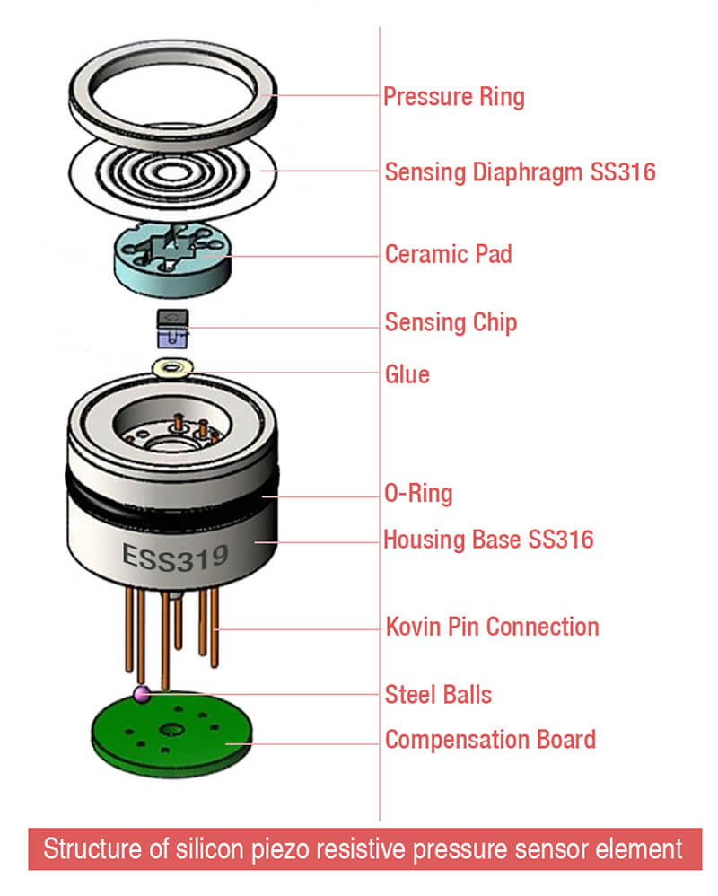
Silicon piezoresistive sensors represent mature technology widely used in industrial pressure measurement. These sensors use a silicon diaphragm with diffused or implanted piezoresistive elements that change resistance when the diaphragm flexes under pressure. Silicon piezoresistive sensors offer excellent accuracy, fast response times, and good repeatability. They’re also generally less expensive than ceramic alternatives in basic configurations.
However, silicon piezoresistive technology faces significant challenges in seawater applications.
Silicon itself is vulnerable to corrosion in aggressive media, particularly in the presence of chlorides. To protect the silicon sensing element, manufacturers typically use oil-filled isolation systems with a corrosion-resistant diaphragm (often stainless steel or titanium) separating the process medium from the silicon chip. Pressure is transmitted through the fill fluid to the protected sensing element.
This oil-filled isolation approach introduces several potential failure modes. The isolation diaphragm can corrode or fatigue over time, particularly in seawater. The fill fluid can leak, degrade, or develop air bubbles, all of which affect measurement accuracy or cause complete sensor failure. Temperature variations cause the fill fluid to expand and contract, which can introduce measurement errors or stress the isolation system.
For long-term seawater immersion, these vulnerabilities present unacceptable reliability risks.
Ceramic-based sensing technologies avoid these isolation system problems by using inherently corrosion-resistant materials in direct contact with the measured medium. Ceramic sensors use alumina (Al2O3) ceramic diaphragms that are essentially impervious to seawater corrosion. The ceramic material withstands chlorides, other salts, and biological activity without degradation, making it ideally suited for marine environments.

Within ceramic sensing technology, two approaches exist: ceramic piezoresistive and ceramic capacitive.
Ceramic piezoresistive sensors use thick-film resistive elements fired directly onto the ceramic diaphragm. When pressure deflects the diaphragm, these resistors change value, producing a measurable signal. This approach combines ceramic’s corrosion resistance with piezoresistive sensing’s proven accuracy and fast response.
Ceramic capacitive sensors, by contrast, measure the capacitance change between the ceramic diaphragm and a fixed electrode as pressure deflects the diaphragm. This technology offers several advantages that proved decisive in my application.
Ceramic Piezoresistive vs Ceramic Capacitive
Both technologies use ceramic as the wetted material — eliminating the corrosion problem. But they differ fundamentally in how they convert pressure to signal, with significant long-term performance implications.
Ceramic Piezoresistive
- Faster dynamic response
- Simpler signal conditioning electronics
- Lower manufacturing cost
- Good for dynamic pressure measurement
- Strain gauges bonded to ceramic surface
- Some susceptibility to EMI in noisy environments
Ceramic Capacitive
- Superior long-term stability
- Better temperature performance
- EMI immune by principle
- Proven in offshore oil & gas
- No bonded gauges — no fatigue failure mode
- Industry standard for marine/desalination
Why Endress+Hauser Core Technology
Not all ceramic capacitive elements are equal. The E+H sensing core represents decades of refinement specifically for demanding industrial and marine applications. Here's what sets it apart:
Decades of Ceramic Capacitive R&D
Not a newcomer to the technology. E+H has been refining ceramic capacitive sensing since the 1980s, with continuous improvement cycles driven by real-world offshore and chemical plant feedback.
0.075%–0.1% FS Accuracy as Standard Spec
Not a marketing claim — a verified, documented specification backed by NIST-traceable calibration. Every element ships with individual calibration data, not batch averages.
Global Proven Track Record
Deployed in chemical plants, offshore platforms, and marine installations worldwide. Thousands of installations in active seawater service provide real-world validation that no lab test can replicate.
High-Purity Alumina Ceramic with Precision Metallization
The ceramic composition and electrode metallization are proprietary formulations optimized for long-term stability. Surface finish and geometry are controlled to micron-level tolerances.
Rigorous QC: Every Element Pressure-Cycled and Temperature-Tested
100% individual testing — not sampling. Each element is pressure-cycled across its full range and temperature-tested before shipment. Elements that drift are rejected, not averaged away.
The Eastsensor Integration Model
The key insight: you don't need to buy a complete E+H transmitter to get E+H sensing performance. The integration model separates the premium sensing element from the cost-effective housing and electronics.
E+H Sensing Core
SS316L Housing Fabrication
Marine-Grade Assembly & Sealing
Calibration & Factory Testing
Material Selection Checklist
Every material choice in a marine sensor either contributes to longevity or becomes a failure point. Use this checklist when specifying or evaluating any seawater-rated sensor:
SS316L housing — molybdenum-enhanced for chloride resistance; 2–3% Mo content is non-negotiable for seawater
Viton/fluoroelastomer O-rings — seawater-compatible; EPDM and nitrile degrade rapidly in marine service
Marine-grade PUR cable jacket — UV + abrasion resistant; rated for continuous seawater immersion
Proper surface finish — smooth Ra ≤ 0.8μm = less fouling + corrosion initiation sites
Post-weld passivation — restore chromium oxide layer after welding; citric acid preferred over nitric
No sharp corners or crevices — eliminate corrosion initiation points; all internal radii ≥ 0.5mm
IP68+ cable glands with strain relief — dynamic loading from currents and wave action requires proper strain management
Anti-seize compounds on all threaded connections — galling between SS surfaces is a real risk; use marine-grade anti-seize
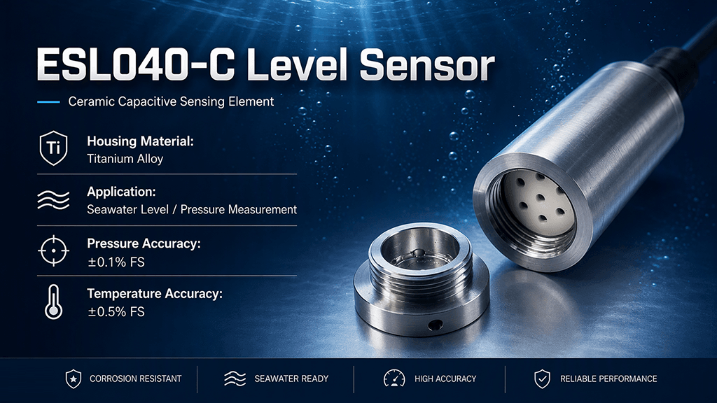
Titanium considered for tropical/warm water — cost premium justified in aggressive environments above 25°C or when maintenance access is limited
Cost-Benefit Snapshot
The hybrid integration model delivers tier-one sensing performance at a fraction of the total cost. Here's the real-world economics:
Lessons Learned from Marine Deployments
Distilled from real-world deployments across offshore platforms, desalination plants, and coastal monitoring networks:
Frequently Asked Questions
Everything you need to know before specifying a seawater level measurement system.
Why can't I use a standard industrial level sensor in seawater?
What makes ceramic capacitive better than piezoresistive for seawater?
Why choose Endress+Hauser as the sensing core?
Is SS316L really enough for seawater applications?
When should I upgrade to titanium housing?
Why RS485 instead of 4–20mA for marine installations?
What is Modbus RTU and why use it?
How do I verify the E+H core is genuine?
How often does the sensor need cleaning?
What's the total cost of ownership?
Ready to Deploy Reliable Seawater
Level Measurement?
Get a custom configuration based on ceramic capacitive sensing with E+H core, tailored to your installation requirements — depth range, cable length, housing material, and output protocol.
📧 [email protected] | 📞 +86-136-2929-7491