Dynamic Pressure Sensor : Complete Guide
When engineers need to capture rapidly changing pressure events—from engine combustions to explosive shockwaves—standard pressure sensors simply can’t keep up. This is precisely where dynamic pressure sensors become indispensable.
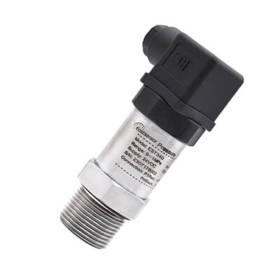
A dynamic pressure sensor is a specialized measurement device designed to detect and record fast-changing pressure variations with exceptional accuracy and speed.
Unlike the static pressure sensor that measure steady-state conditions, these sensors excel at capturing transient pressure events occurring in milliseconds or even microseconds.
What is a Dynamic Pressure Sensor?
Dynamic pressure sensor is a precision instrument that converts rapidly fluctuating pressure variations into electrical signals for measurement and analysis.
These sensors function as highly responsive pressure transducers, specifically engineered to track pressure changes that occur within fractions of a second.
In essence, they serve as the “eyes and ears” for monitoring transient pressure events that would otherwise be invisible to conventional measurement tools.
Core Function and Purpose
The primary function of dynamic pressure measurement is to capture time-varying pressure phenomena with minimal distortion.
Unlike regular pressure sensor or pressure gauge that display a single reading, dynamic pressure sensors continuously track and record pressure fluctuations across time. Moreover, they maintain accuracy even when pressure changes occur at frequencies ranging from several hertz to hundreds of kilohertz.
This capability makes them invaluable for applications where understanding the exact timing and magnitude of pressure variations is critical.
Dynamic vs. Static
When it comes to comparison between dynamic and static pressure sensor, while both types measure pressure, their design philosophies differ fundamentally. Static pressure sensors are optimized for stable, long-term measurements of constant or slowly changing pressures. In contrast, dynamic sensors prioritize speed and frequency response above all else.
The differences extend beyond just response time. Static sensors typically offer excellent zero stability and can maintain calibration for extended periods under constant pressure. However, dynamic pressure sensors sacrifice some long-term stability in exchange for the ability to respond almost instantaneously to pressure changes.
Additionally, static sensors often include temperature compensation for drift correction, whereas dynamic sensors focus on minimizing any delay between the actual pressure event and its measurement.
Quick Comparison
Feature Static Pressure Sensor Dynamic Pressure Sensor
Primary Focus Long-term stability & accuracy Speed & frequency response
Response Time Milliseconds to seconds Microseconds to milliseconds
Frequency Range DC to ~10 Hz 1 Hz to 500+ kHz
Zero Stability Excellent over time Limited; subject to drift
Signal Type Steady, low-noise Rapidly varying, higher noise
Static Measurement Yes, primary use No (piezoelectric types)
Temperature Compensation Extensive Limited
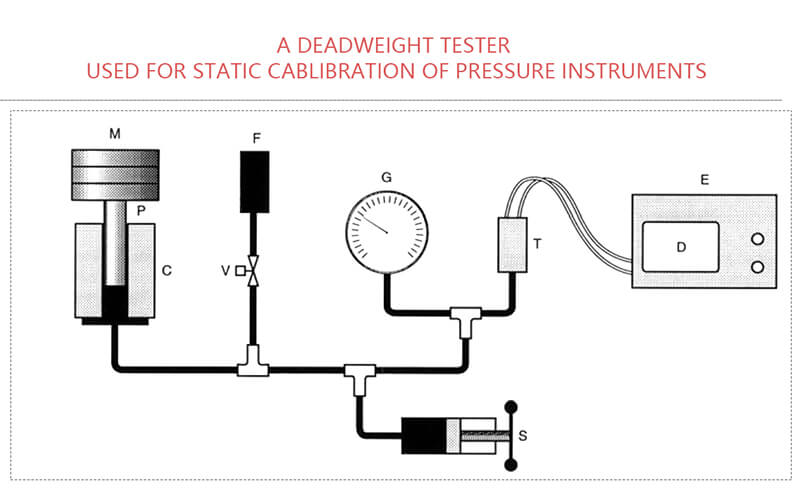
Calibration Complexity Simple (deadweight tester) Complex (shock tube, etc.)
Typical Applications Process control, tank levels Engine testing, ballistics
Pressure Range Broad, well-compensated Application-specific
How Dynamic Pressure Sensors Work
The working principle behind most dynamic pressure sensors is remarkably elegant. When pressure acts upon the sensor’s diaphragm or sensing element, it generates a mechanical deformation.
This deformation is then converted into an electrical signal through various methods—whether piezoelectric charge generation, resistance change, or capacitance variation.

Importantly, the entire conversion process happens with minimal time delay, typically measured in microseconds. The resulting electrical output directly correlates to the applied pressure, creating a real-time electrical representation of the dynamic pressure event.
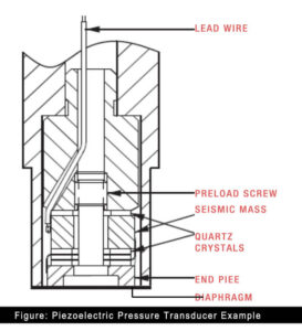
Piezoelectric Pressure Sensors
Piezoelectric pressure sensors represent the most widely used technology for high-frequency dynamic measurements. These sensors exploit a remarkable property of certain crystalline materials—primarily quartz, tourmaline, and specialized ceramics—that generate electrical charge when subjected to mechanical stress.
When pressure acts upon a piezoelectric crystal, the mechanical force causes minute deformations in the crystal lattice structure. This deformation displaces the positive and negative charge centers within the material, creating an electrical charge on the crystal’s surface.
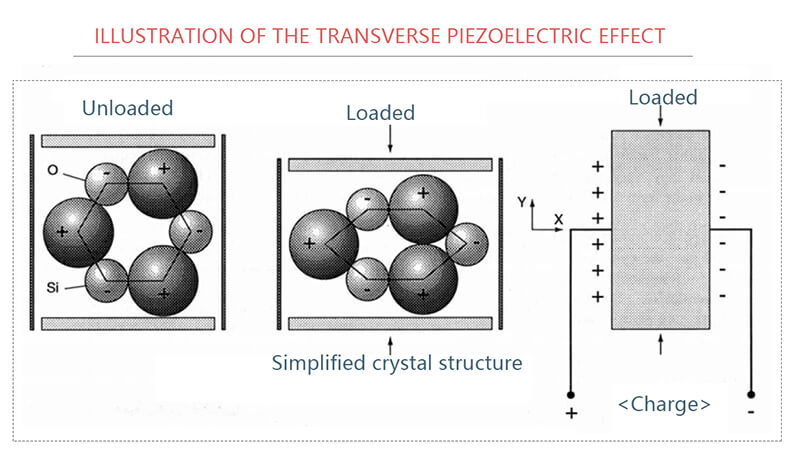
The beauty of this mechanism lies in its incredible speed: the charge appears almost instantaneously with the applied force, enabling response times measured in microseconds.
It makes piezoelectric pressure sensors achieved natural frequencies often exceeding 500 kHz, making them ideal for capturing explosive detonations, engine knock, and shock waves.
However, this technology has an important limitation: the generated charge inevitably leaks away through the sensor’s internal resistance. This means piezoelectric sensors cannot truly measure static pressure—they excel exclusively at measuring pressure changes and dynamic events.
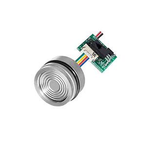
Piezoresistive Pressure Sensors
Piezoresistive sensor technology operates on a different principle: certain semiconductor materials exhibit dramatic resistance changes when subjected to mechanical strain. Unlike metallic strain gauges with modest sensitivity, piezoresistive materials—particularly doped silicon—can achieve sensitivity factors 50 to 100 times higher.
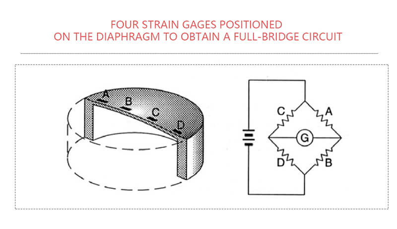
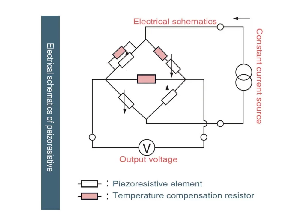
In a piezoresistive pressure sensor, a thin silicon diaphragm flexes minutely under applied pressure. Piezoresistive elements embedded in the diaphragm change their electrical resistance in proportion to the strain they experience. These resistance changes are detected using a Wheat bridge circuit that converts them into a measurable voltage output.
In this case, piezoresistive sensors balance this trade-off effectively, achieving frequency responses from DC to approximately 50 kHz while maintaining the ability to measure both static and dynamic pressures—a significant advantage over piezoelectric types.
Lick to find more details: Piezoelectric VS Piezo-resistive
Key Differences between Piezoresistive and Piezoelectric
Feature Piezoresistive Sensors Piezoelectric Sensors
How They Work Measure resistance changes in silicon under strain. Generate electric charge when crystals are squeezed.
Static Pressure ✅ Can measure steady pressure (e.g., tire pressure). ❌ Only measures changing pressure (e.g., engine vibrations).
Accuracy 0.1%-0.5%-1.0%/FS 1.0%-2.0%-3.0%/F
Overpressure 2X to 50X 2X to 50X
Size Tiny (as small as 0.055" diameter). Bulky (smallest is ~0.19" diameter).
Temperature Range -320°F to 1000°F (unamplified). -320°F to 1040°F (limited by crystal type).
Vibration Sensitivity Low (0.00015 PSI/g). High (0.002 PSI/g).
Cost (Sensor) Low-Medium XX Medium-High XXX
Cables Standard shielded wires (cheap). Special low-noise cables (expensive).
Durability Rugged, ideal for harsh environments. Sensitive to installation errors and shock.
Power Needs Requires external power (5–15V) Self-powered (no external juice needed)
Signal Output Voltage (0–10V) or current (4–20mA). Charge or voltage (needs amplifiers).
Industry - Process control in industrial settings
- HVAC systems
- Automotive applications (tire pressure, engine management)
- Medical devices (blood pressure monitoring)
- Weather stations (barometric pressure)
- Hydraulic and pneumatic systems- Engine combustion analysis
- Blast pressure measurement
- Shock wave studies
- Aerodynamics and wind tunnel testing
- Ballistics and explosive testing
- Hydraulic system dynamics
- Turbine blade pressure measurement
Construction 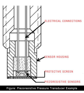
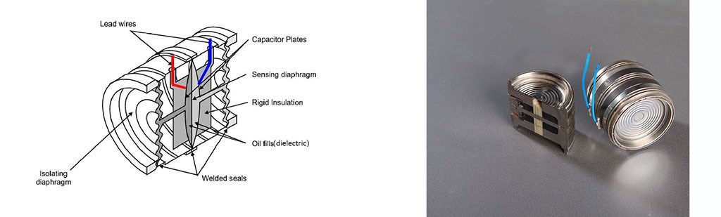
Capacitive Pressure Sensors
Capacitive sensors employ a flexible diaphragm as one plate of a capacitor, with a fixed electrode forming the other plate. As pressure deflects the diaphragm, the gap between the plates changes, altering the capacitance. Modern micromachined capacitive sensors can achieve remarkably small masses and high natural frequencies, with some designs reaching beyond 100 kHz.
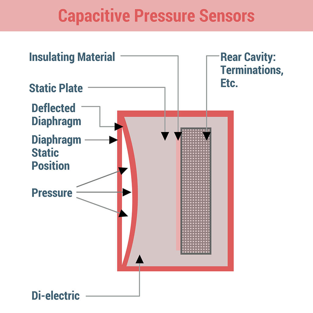
The capacitive approach offers excellent sensitivity and lower temperature sensitivity compared to other technologies. However, the electronics required to detect tiny capacitance changes add complexity, and stray capacitance from cables can introduce errors if not properly managed.
Key Differences: Piezoresistive vs Piezoelectric Sensors for Dynamic Pressure Measurement
1. Frequency Response and Measurement Range
Piezoresistive sensors can measure pressure from DC (zero frequency) up to approximately 50 kHz. This means they can capture both steady-state pressures and rapidly changing pressures. You can measure something that changes slowly (like gradual pressure build-up) or something that changes very fast (like pressure pulses in an engine).
Piezoelectric sensors can only measure AC (alternating/changing) pressures, typically starting from around 1 Hz and going up to several hundred kHz or even MHz.
They cannot measure static (non-changing) pressure at all. The signal will drift back to zero if the pressure stays constant, even if that constant pressure is high.
Practical Impact: If you need to know both the baseline pressure AND the pressure fluctuations (like measuring vibrations on top of a steady pressure), you must use piezoresistive. Piezoelectric only tells you about the changes.
2. What Each Sensor Actually Measures
Piezoresistive sensors measure absolute pressure values. They tell you “the pressure is 100 kPa right now, and it just spiked to 105 kPa.” You get the complete pressure profile over time.
Piezoelectric sensors measure only pressure changes. They tell you “the pressure just increased by 5 kPa” but won’t tell you what the starting pressure was. The output signal represents the rate of pressure change, not the pressure itself.
In an explosion test, piezoresistive shows you the entire pressure curve from ambient to peak and back down. Piezoelectric only shows you the dynamic shock wave but loses the baseline reference.
3. Signal Output Characteristics
Piezoresistive sensors produce a continuous DC voltage or current output that’s proportional to the applied pressure. The signal is stable and can be read with standard data acquisition equipment. The output stays at a certain level as long as the pressure remains constant.
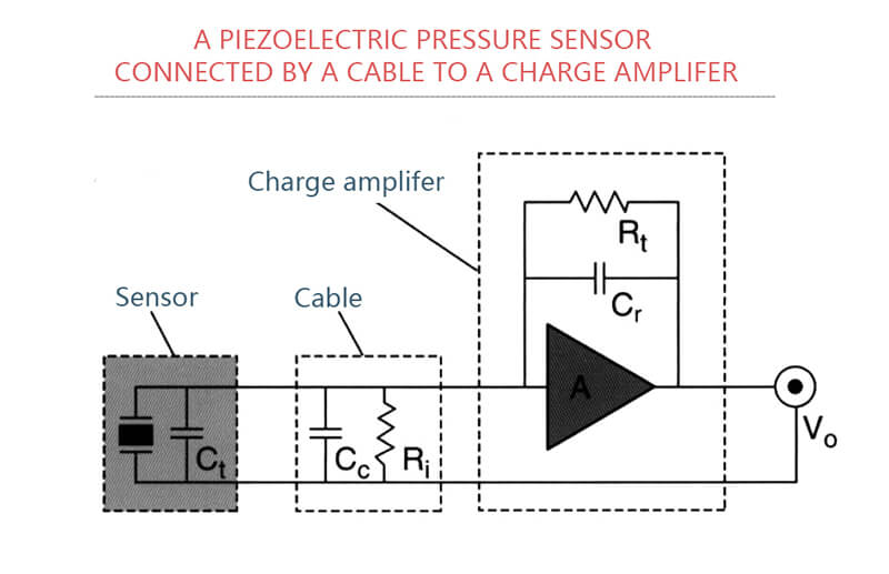
Piezoelectric sensors generate an electrical charge in response to pressure changes. This charge leaks away over time, so the sensor requires special charge amplifiers or impedance converters. If you try to measure a steady pressure, the signal will decay to zero even though the pressure hasn’t changed. Piezoresistive sensors are easier to integrate into measurement systems and don’t require specialized amplifiers. Piezoelectric sensors need more complex signal conditioning equipment.
4. Sensitivity and Resolution
Piezoresistive sensors offer moderate sensitivity but excellent low-frequency resolution. They can detect very small, slow pressure changes accurately. Typical sensitivity might be 1-10 mV per kPa of pressure, for example: ESS319 (0-10kpa) will give signal response when 5pa pressure applied, which mean resolution is 5pa/10kpa=0.0005.
Click to check Relationship between Sensitivity and Resolution
Piezoelectric sensors offer extremely high sensitivity to rapid pressure changes, making them ideal for detecting tiny high-frequency vibrations or shock waves. They can detect pressure changes as small as 0.001 psi in the right frequency range.
- For measuring small vibrations superimposed on high background pressure (like combustion noise in an engine), piezoelectric excels.
- For measuring gradual pressure variations with occasional spikes, piezoresistive is better.
5. Temperature Sensitivity and Drift
Piezoresistive sensors are more sensitive to temperature changes. Temperature affects the resistance of the sensing element, which can cause measurement errors. Good piezoresistive sensors include temperature compensation, but some drift is inevitable in extreme temperature swings.
Piezoelectric sensors have excellent temperature stability for dynamic measurements because they only respond to changes. Temperature drift mainly affects the baseline, which you’re not measuring anyway. Some piezoelectric materials (like quartz) are very thermally stable. In high-temperature applications with rapid thermal cycles (like near combustion chambers), piezoelectric sensors often maintain better accuracy for dynamic measurements.
6. Cost and Durability
Piezoresistive sensors are generally more affordable for general-purpose applications They’re mechanically simpler but can be damaged by overpressure events.
Piezoelectric sensors tend to be more expensive but are extremely rugged and can withstand severe shock and vibration. They have fewer mechanical failure modes.
If you need a durable sensor for harsh, high-frequency environments and don’t need DC response, piezoelectric offers better long-term reliability despite higher initial cost.
Where Each Excels Piezoresistive & Piezoelectric
| Piezoresistive sensors are preferred for: | Piezoelectric sensors are preferred for: |
|---|---|
| Aircraft airspeed measurement (need both static and dynamic pressure) | Blast and explosion testing (extremely fast events) |
| HVAC system monitoring (pressure changes slowly) | Engine knock detection (high-frequency vibrations) |
| Medical devices (blood pressure monitoring) | Turbine blade pressure measurements (fast fluctuations) |
| Process control (need absolute pressure readings) | Acoustic measurements and sound pressure |
| Automotive tire pressure monitoring | High-frequency vibration analysis |
| Any application requiring DC response or baseline pressure information | Shock and impact testing |
| Choose Piezoresistive if you need: | Choose Piezoelectric if you need: |
|---|---|
| Both static and dynamic pressure measurements | Only dynamic/changing pressure measurements |
| DC to moderate frequency response (up to 50 kHz) | Very high frequency response (>50 kHz) |
| Absolute pressure values | Extremely high sensitivity to rapid changes |
| Simpler signal conditioning | Superior temperature stability |
| Lower cost | Maximum durability in shock/vibration environments |
Key Applications and Industries
Dynamic pressure sensors have become indispensable instruments across numerous industries where understanding rapidly changing pressure phenomena directly impacts product performance, safety, and efficiency.
Automotive Industry
The automotive sector represents one of the largest markets for dynamic pressure sensor applications, particularly in engine development and optimization.
- Engines combustion
- Engine emissions
- Exhaust system
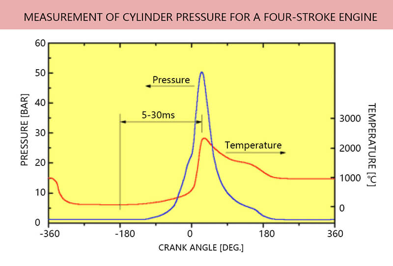
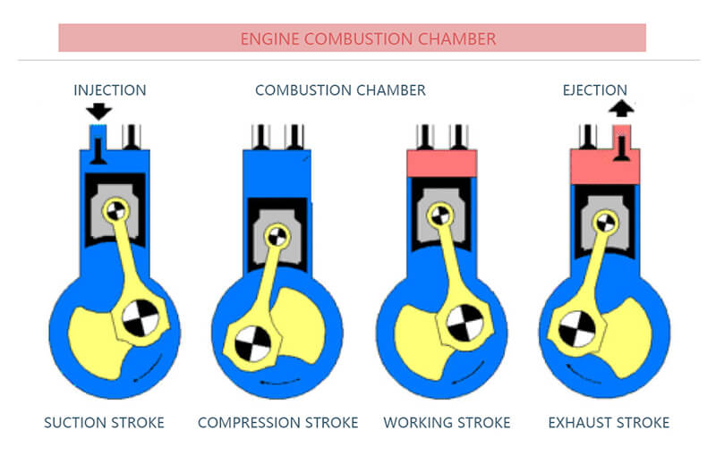
Modern combustion engines operate under extraordinarily complex conditions, with cylinder pressures reaching 20 MPa and changing thousands of times per minute.
Engineers utilize dynamic pressure sensors mounted directly in the combustion chamber to capture detailed pressure-time histories during each combustion cycle. This real-time combustion analysis reveals critical information about fuel injection timing, air-fuel mixture quality, and ignition efficiency.
By analyzing the pressure curve’s shape, engineers can detect engine knock—a destructive phenomenon where uncontrolled combustion creates damaging pressure oscillations at frequencies up to 20 kHz.
Furthermore, pressure sensors for automotive industry applications enable the development of engines that meet increasingly stringent emissions regulations while maintaining optimal fuel economy.
Even minor improvements in combustion efficiency, validated through dynamic pressure measurement, can translate into millions of dollars in fuel savings and reduced environmental impact across a manufacturer’s fleet.
Beyond engine cylinders, automotive applications extend to exhaust system pressure monitoring, fuel injection pressure measurement (now exceeding 200 MPa in modern diesel systems), and airbag deployment testing where pressures must be precisely characterized to ensure occupant safety during crashes.
Aerospace
The aerospace industry relies heavily on dynamic pressure measurements to ensure aircraft safety and performance.
- Wind tunnel testing
- Jet engine development
- Flight testing
- Other spacecraft applications
During wind tunnel testing, engineers position hundreds of dynamic pressure sensors across aircraft models to map the pressure distribution at various flight conditions. These measurements reveal aerodynamic forces, identify potential structural stress points, and validate computational fluid dynamics models.
In jet engine development, dynamic pressure sensors withstand extreme temperatures and vibrations while monitoring compressor stage pressures, combustion chamber dynamics, and turbine performance.
A pressure sensor for aerospace applications must maintain accuracy while enduring temperature swings from -50°C to over 500°C, making sensor selection and installation critical engineering challenges.
Flight testing represents perhaps the most demanding aerospace application. Instrumented aircraft carry dynamic pressure sensors to measure everything from cabin pressurization dynamics to control surface aerodynamic loads during extreme maneuvers.
For spacecraft applications, sensors must survive launch vibrations, function in vacuum conditions, and provide reliable data during atmospheric reentry when pressure changes occur in milliseconds.
Manufacturing
Modern manufacturing processes increasingly depend on precise pressure control and monitoring.
- Plastic injection molding
- Hydraulic systems
- Die-casting operations
In plastic injection molding, cavity pressure determines product quality, dimensional accuracy, and surface finish. Dynamic pressure sensors installed in the mold cavity track the pressure evolution as molten plastic fills the cavity, providing real-time feedback for process optimization.
Manufacturers have discovered that monitoring injection pressure dynamics can reduce scrap rates by 15-30% while improving cycle times.
Hydraulic systems powering industrial machinery, metalworking presses, and mobile equipment require dynamic pressure monitoring to prevent catastrophic failures and optimize performance.
When a hydraulic pump begins to cavitate—a condition where vapor bubbles form and collapse violently—dynamic pressure sensors detect the characteristic high-frequency pressure pulses (often above 10 kHz) that precede component damage.
This early warning capability prevents expensive downtime and extends equipment life significantly.
Die-casting operations, where molten metal is forced into molds at pressures exceeding 100 MPa, similarly benefit from dynamic pressure monitoring to ensure consistent product quality and identify process variations before they produce defective parts.
Research and Development
Research institutions and universities employ dynamic pressure sensors to advance scientific understanding across diverse fields.
- Ballistics research
- Fluid dynamics laboratories
Ballistics researchers measure chamber pressures in firearms and artillery to optimize propellant formulations and ensure safe operating pressures. These applications demand sensors capable of surviving pressure amplitudes reaching 800 MPa with frequency content extending to several hundred kilohertz.
Fluid dynamics laboratories use dynamic pressure sensors to study turbulence, shock wave interactions, and supersonic flow phenomena.
Medical Devices
The medical field has increasingly adopted dynamic pressure measurement for both diagnosis and device development.
- Diagnosis of blood monitoring
- Orthopedic research
- Biomechanics research
Blood pressure monitoring traditionally captures only systolic and diastolic values, but researchers have found that the dynamic pressure waveform contains valuable diagnostic information about arterial stiffness and cardiovascular health. Specialized medical-grade dynamic pressure sensors enable continuous monitoring of patients in critical care settings.
Orthopedic research utilizes miniature dynamic pressure sensors to measure contact pressures in artificial joints during motion, providing insights that improve prosthetic design and surgical techniques. Similarly, biomechanics researchers embed pressure sensors in footwear to analyze gait patterns and optimize athletic performance or design better orthotics for patients with mobility challenges.
Common Challenges and Troubleshooting
Even the most sophisticated dynamic pressure sensors can deliver unreliable data when installation or environmental factors introduce errors. Understanding common pressure sensor problems and their solutions enables engineers to achieve accurate measurements and avoid costly mistakes in critical applications.
Signal Noise and Electromagnetic Interference
Electrical noise represents one of the most prevalent challenges in dynamic pressure measurement.
Because dynamic sensors often produce low-level signals measured in millivolts, they become susceptible to electromagnetic interference from nearby motors, ignition systems, or switching power supplies.
This interference manifests as erratic spikes, high-frequency ripple, or baseline drift in the measurement signal.
The solution begins with proper cable selection and routing. Always use shielded cables with the shield grounded at only one end—typically at the amplifier—to prevent ground loops that can introduce noise. If interference persists, consider using sensors with integrated electronics that output high-level signals less vulnerable to pickup, or employ differential signal transmission techniques.
Additionally, ensure proper grounding of all measurement equipment to a common reference point. Poor grounding creates multiple current paths that generate voltage differences appearing as measurement errors.
In electrically noisy environments such as engine test cells, twisted-pair shielded cables and differential amplifiers provide superior noise rejection compared to single-ended configurations.
Temperature Effects: The Hidden Variable
Many modern sensors incorporate built-in temperature compensation, but this compensation assumes gradual, uniform temperature changes. Rapid thermal transients or temperature gradients across the sensor can overwhelm compensation circuits, producing significant errors.
In high-temperature applications like exhaust system monitoring or combustion analysis, thermal shock—sudden exposure to extreme temperatures—can permanently damage unprotected sensors.
Preventive measures include selecting sensors rated for your application’s temperature extremes and allowing adequate warm-up time for thermal stabilization. When measuring in high-temperature environments, use water-cooled sensor adapters or thermal barriers to protect the sensing element before wetted with medium.
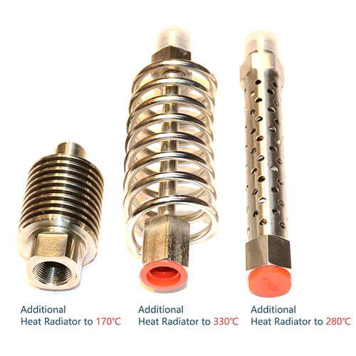
For critical measurements, monitor sensor body temperature and apply additional correction factors based on calibration data at multiple temperatures.
Mechanical Mounting Issues
Improper mechanical installation ranks among the most common sources of measurement error, yet it often goes unrecognized. Vibration and mechanical shock transmitted through the mounting structure can generate spurious signals, particularly in acceleration-sensitive sensors.
This problem becomes especially severe in automotive and aerospace applications where vibration is unavoidable.
Flush mounting provides the best solution—installing the sensor so its diaphragm sits perfectly level with the surface where pressure is measured. Recessed mounting creates a cavity that acts as an acoustic resonator, amplifying certain frequencies and distorting the measured pressure.

Even small cavities (just a few millimeters deep) can introduce resonances at frequencies within the measurement range, creating mysterious peaks in what should be smooth pressure curves.
Mounting torque also matters critically. Insufficient torque allows pressure leakage and creates unreliable sealing, while excessive torque can stress the sensor housing and shift calibration or even crack the sensing element.
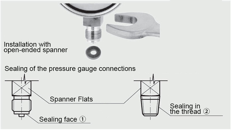
Sealing Procedures
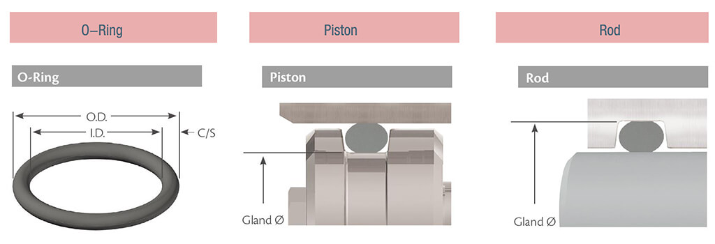
Never overlook the importance of proper sealing. Use appropriate O-rings or gaskets matched to the pressure medium and temperature range. Chemical incompatibility between sealing materials and the measured fluid can cause seal degradation, leading to leaks and contamination that compromise measurement accuracy and potentially damage expensive sensors.
Cable Management and Electrical Connections
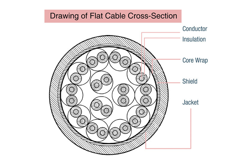
Cabling represents a critical yet often underestimated aspect of successful installation. For piezoelectric sensors, use only low-noise coaxial cables specifically designed for charge measurements. Standard instrumentation cables possess insufficient insulation resistance, causing excessive charge leakage that limits low-frequency response and introduces measurement drift.
Keep cable lengths as short as practical—typically under 10 meters for piezoelectric sensors unless using amplified sensor designs with integrated electronics. Longer cable runs increase capacitance, reducing sensitivity and potentially degrading signal-to-noise ratio.
FAQ: Dynamic Pressure Measurement
What is the difference between static and dynamic pressure?
Static pressure exists whether fluid moves or not—like air pressure in a tire. Dynamic pressure only exists during motion. Stick your hand out a car window: that force you feel is dynamic pressure from moving air. No movement, no dynamic pressure.
How does a pitot tube measure dynamic pressure?
It compares two pressures: one opening faces the airflow (total pressure), another measures from the side (static pressure). The difference is dynamic pressure, which indicates flow speed. That’s how aircraft measure airspeed.
What industries commonly use dynamic pressure measurement?
Aviation (airspeed, wind tunnels), HVAC (ventilation monitoring), automotive (aerodynamic testing), marine (vessel speed), and industrial processes (gas flow, combustion optimization). Anywhere fluid speed matters.
How accurate are dynamic pressure sensors?
Industrial sensors: ±0.5% to ±2%. Laboratory instruments: even better. Accuracy depends on calibration (every 6-12 months for critical uses), proper installation, and stable conditions. Match accuracy to your application—don’t overpay for precision you don’t need.
Can dynamic pressure sensors work in harsh environments?
Yes. Ruggedized sensors handle -40°C to +125°C+, vibration, moisture, and corrosive chemicals. Look for stainless steel construction and IP67/IP68 ratings. Extreme applications (jet engines, deep sea) need specialized designs. Always verify specs match your conditions.
Conclusion
Dynamic pressure sensors have become essential instruments for capturing rapidly changing pressure phenomena across automotive, aerospace, manufacturing, and research applications. Understanding the fundamental differences between dynamic and static sensors, selecting appropriate sensing technologies—whether piezoelectric, piezoresistive, or capacitive—and following proper installation and calibration procedures are critical for achieving accurate, reliable measurements.
Ready to implement dynamic pressure measurement in your application? Contact our technical specialists for personalized guidance on sensor selection, installation support, and calibration services tailored to your specific requirements.