Pressure Sensor Process Connection
Introduction
An accurate and reliable process connection ensures a seamless interface between the pressure sensor and the equipment being monitored, enabling precise readings and helping to prevent leaks or other issues that could compromise the system’s performance.
Each process connection method offers unique benefits depending on the specific requirements. In this article, I will guide you through the four main types of process connection methods—threaded connections, flanged connections, welded connections, and submersible connections—and highlight their key features:
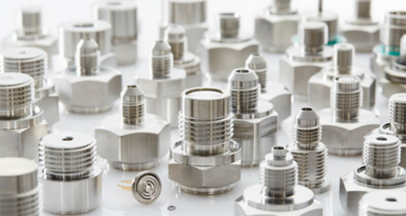
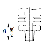
Threaded Connections
Threaded connections are a widely used and cost-effective solution for joining pressure sensors to equipment. They offer flexibility in installation and can easily be adjusted or removed in case of maintenance. Some common thread types include NPT, BSP, Metric and PT Threads. Tightening torque should be carefully considered when installing threaded connections, as it directly impacts the effectiveness of the seal.
The most widely used thread types for pressure sensor connections include
- National Pipe Thread (NPT),
- British Standard Pipe (BSP),
- Metric threads. Standards:
- PT (Pipe Taper) threads,
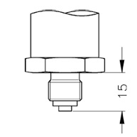
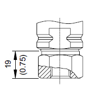
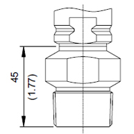
| 1/2"BSP MALE | 1/2"G EN837 DIN16288 |
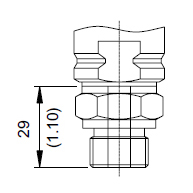 | 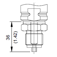 |
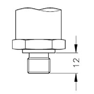
| 1/2"NPT MALE | 1/4"NPT MALE |
 |  |
For more details about threads connection, you can check
- 4 Types of Thread Process Connections – Part 1/2
- 4 Types of Thread Process Connections – Part 2/2
- The Ultimate Knowledge about Thread for Process Connection
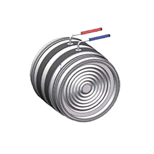
Flanged Connections
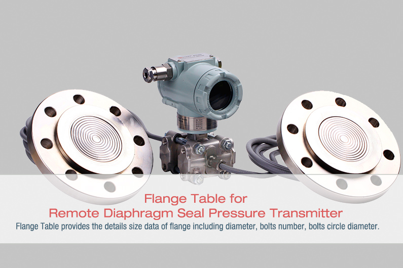
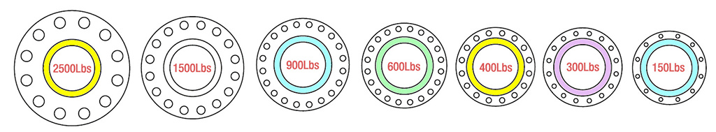
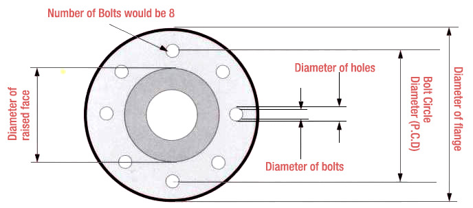
Flanged connections provide a reliable and robust solution, particularly for high-pressure applications. Consisting of two flanges bolted together, these connections create a strong, pressure-tight seal, while still allowing easy disassembly for maintenance. ANSI, DIN, and JIS are popular flange standards, and proper selection of gasket type and material—depending on operating conditions—plays a crucial role in ensuring a secure connection.
Flanged process connections bring numerous advantages to the table, making them popular choices for various industries and applications. Their notable benefits include:
- Robust sealing: Flanges provide a strong, pressure-tight seal, suitable for high-pressure applications.
- Easy maintenance: The bolted design allows easy disassembly for maintenance or replacement purposes.
- Compatibility: Flanges are compatible with different materials and can be used for various pipe sizes and pressure ratings.
Regarding types of flanges, several common options are available based on industry needs and specific requirements. Some popular flange types include:
- Welding Neck: Known for their durability and high-pressure resistance, these flanges are often used in extreme conditions.
- Slip-On: Economical and easy to install, slip-on flanges are versatile and suitable for low-pressure applications.
- Socket Weld: These flanges offer a secure connection for smaller pipes in high-pressure applications.
- Lap Joint: Lap joint flanges facilitate easy disassembly for systems requiring regular maintenance
 .
. - Threaded: These flanges enable connection to threaded pipes without welding, making them suitable for low-pressure applications and instances where welding is unfeasible.
When it comes to flanged process connection installation, please also keep the following tips in mind:
- Ensure proper alignment and leveling of the flange faces to achieve a uniform seal.
- Select the appropriate gasket type and material based on the application, pressure, and temperature requirements.
- Follow the recommended bolt-tightening procedure and torque values to avoid over-tightening or under-tightening, which can compromise the seal.
- Choosing the right flange type for your application requires careful consideration of factors such as pressure and temperature ratings, pipe size, material compatibility, and maintenance requirements. Assess the specific needs of your application and compare them to the features and limitations of each flange type to determine the best option.
Click to check more details about Flange
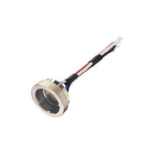
Welded connections
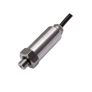
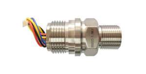
Welded connections are an excellent choice for high-pressure and high-temperature applications, wherein durability and reliability are of paramount importance. By permanently fusing the pressure sensor to the equipment, we create a leak-proof bond that enhances system integrity. Various welding techniques, such as Tungsten Inert Gas (TIG) and Metal Inert Gas (MIG), are used based on the materials and work environment. However, the permanence of welded connections may make maintenance or sensor replacement more challenging than in other connection types.
Check More: ESS322 All Welded Pressure Sensor
Welded process connections provide several benefits that make them suitable for high-pressure and demanding applications:
- Superior strength: Welded connections form a strong, permanent bond between the pressure sensor and the equipment or piping.
- Leak-proof: By eliminating potential leak points associated with threaded or flanged connections, welded connections provide an airtight seal.
- High-pressure and high-temperature compatibility: Welded connections are designed to withstand extreme pressure and temperature conditions.
Various welding techniques can be employed for welded process connections, depending on the materials and application requirements:
- Tungsten Inert Gas (TIG) Welding: A precise welding technique suitable for thin materials and exotic metals, TIG welding offers excellent control and a clean finish.
- Metal Inert Gas (MIG) Welding: MIG welding is a versatile method, ideal for a wide range of materials and thicknesses, providing increased productivity and lower distortion levels.
- Shielded Metal Arc Welding (SMAW): SMAW is a common technique for field welding and joining thick and heavy materials, offering portability and strong welds.
When dealing with high-pressure applications, consider the following factors for welded process connections:
- Material compatibility: Select welding materials that are compatible with the pressure sensor and the equipment or piping to avoid potential failure points due to material incompatibility.
- Preparatory work: Proper cleaning and preparation of the surfaces to be welded are vital for achieving a sturdy connection and minimizing the risk of contamination or defects.
- Heat treatment: In certain cases, post-weld heat treatment may be necessary to relieve stress and improve the connection’s structural integrity.
To ensure the reliability of welded connections, adopt these best practices:
- Qualification of welders: Employ qualified welders with the necessary training and certifications to guarantee the quality of the welded connection.
- Visual inspection: Conduct regular visual inspections of the welded connections to identify any surface defects or irregularities.
- Non-destructive testing (NDT): Techniques such as ultrasonic testing, radiographic testing, or dye penetrant testing can be used to identify subsurface defects in welded connections that may not be visible to the naked eye.
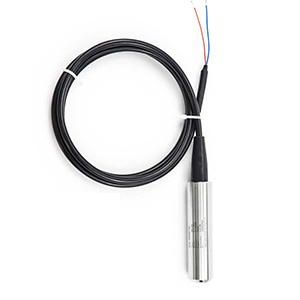
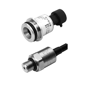
Submersible connections
Submersible connections are designed to perform efficiently in underwater or fluid-immersed environments. These connections are watertight, corrosion-resistant, and capable of withstanding higher-pressure levels. A robust sealing system, typically comprising O-rings or hermetic seals, is essential for maintaining the reliability of submersible connections. Periodic inspection for signs of wear and corrosion is crucial to ensure optimal performance.
Submersible process connections offer several advantages that make them ideal for underwater or fluid-immersed environments:
- Watertight seals: Engineered to function efficiently in submerged conditions, submersible connections provide reliable watertight seals.
- Corrosion resistance: Materials used for submersible process connections are often corrosion-resistant, ensuring longevity and functionality in harsh circumstances.
- External pressure compensation: Submersible pressure sensors can account for external pressure changes, offering accurate readings in submerged applications.
Submersible pressure sensors are employed in a variety of applications:
- Water and wastewater treatment plants: Monitoring water levels, flow rates, and pressure in submerged pipes and tanks.
- Oceanographic research and marine industries: Supporting underwater exploration, subsea equipment, and environmental studies.
- Flood monitoring systems: Gauging water levels and providing early warning signals during floods.
To ensure optimal installation and maintenance of submersible process connections, consider the following tips:
- Cable selection: Choose a cable that is specifically designed for underwater use, considering factors such as tensile strength, corrosion resistance, and chemical compatibility.
- Cable entry seal: Ensure that the cable entry point into the pressure sensor housing is watertight to prevent moisture ingress.
- Use adequate cable supports: Properly support and secure cables to prevent excessive strain and potential damage to the connection.
- Regular inspection: Periodically inspect the submerged connections for any signs of wear, damage, or corrosion and promptly rectify any issues to ensure continued reliability.
Challenges encountered in underwater pressure sensor connections include:
- Material selection: Identifying materials that can withstand harsh underwater conditions, providing corrosion resistance and ensuring long-lasting performance.
- Proper sealing: Ensuring the connections remain watertight and do not compromise the overall system integrity.
- Signal interference: Overcoming potential signal interference or attenuation due to the effects of water or other environmental factors.
Temperature Effects on Process Connections
Let’s explore the effects of temperature fluctuations on process connections, material selection for temperature extremes, temperature compensation in pressure sensors, and avoiding thermal cycling issues in process connections.
Impact of temperature fluctuations on process connections: Temperature changes can affect process connections in various ways, including:
Thermal expansion and contraction:
Materials expand and contract due to temperature fluctuations, potentially leading to loose connections or leaks.
Seal degradation: Temperature changes can affect the performance and longevity of seals and gaskets in the connections.
Material limitations: Some materials may lose mechanical strength or undergo structural changes when exposed to extreme temperatures, compromising the connection’s integrity.
Material selection for temperature extremes:
Selecting materials capable of withstanding temperature extremes is crucial for maintaining the reliability of process connections. Common materials include:
- Stainless steel: Offers excellent resistance to a wide range of temperatures and maintains its mechanical properties.
- High-temperature alloys (Inconel, Hastelloy): These alloys are suitable for applications with extreme temperatures and offer excellent resistance to oxidation and corrosion.
- PTFE (Teflon): For seals and gaskets, PTFE exhibits excellent resistance to temperature extremes and chemical compatibility.
Wrap up
In today’s guide, we discuss four different ways to connect pressure sensors to equipment: threaded connections, flanged connections, welded connections, and submersible connections. Each method has its own benefits and requires specific installation and maintenance procedures. Temperature changes can also affect these connections, and the article suggests using special materials like alloys and PTFE for seals and gaskets to handle extreme temperatures.
Threaded connections involve screwing the sensor into the equipment, while flanged connections use bolts to attach the sensor to a flange on the equipment. Welded connections involve fusing the sensor to the equipment, and submersible connections are designed for use in liquids and require a waterproof seal.
The article provides tips on properly installing and maintaining each type of connection, including using appropriate torque values and checking for leaks. It also emphasizes the importance of selecting the suitable materials for the temperature range of the equipment, as well as regularly inspecting and replacing worn or damaged seals and gaskets. Overall, this guide provides useful information for anyone looking to connect pressure sensors to their equipment safely and effectively.