Introduction
Pressure Transmitter Manifold valves consolidate multiple single valves into a single valve block. This method allows the user to use these multiple valves in a single block to perform multiple functions and tasks without removing the Differential Pressure Transmitter (DP) from its installed position. The single block minimizes the number of connections and potential leak points which makes for a more secure process connection.
A valve manifold is often used with a DP transmitter so that it can isolate and equalize pressure exerted on the transmitter whenever any process is taking place. This valve is manual, but it is useful for calibration and maintenance purposes. Find the details about DP Transmitter Application. And the Basics of DP Transmitter.
The 3 Valve Manifold
This device ascertains that the capsule does not exceed beyond its designated range and does not isolate the pressure transmitter manifold from the entire process. As the name implies, the 3-valve manifold actually comprises of three valves— a high pressure block valve, a lower pressure block valve and an equalizing valve.
The block valves work together to isolate the instruments. The equalizing valve, placed in between the low and high transmitter process connections, ensures equal pressure on both sides.
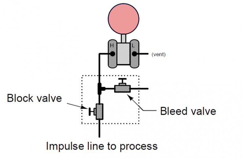
Study the image below depicting a 3 valve manifold shown within the dotted box. Often, an additional valve, referred to as the bleed valve, emits the trapped pressure into the atmosphere.
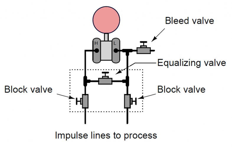
Though the image above actually shows four valves, a standard 3 valve manifold only features two block valves and one equalizing valves as mentioned earlier; the block valve is often not included.
Also, this image depicts the three valves as completely separate devices that have been connected with each other and to the transmitter through tubing.
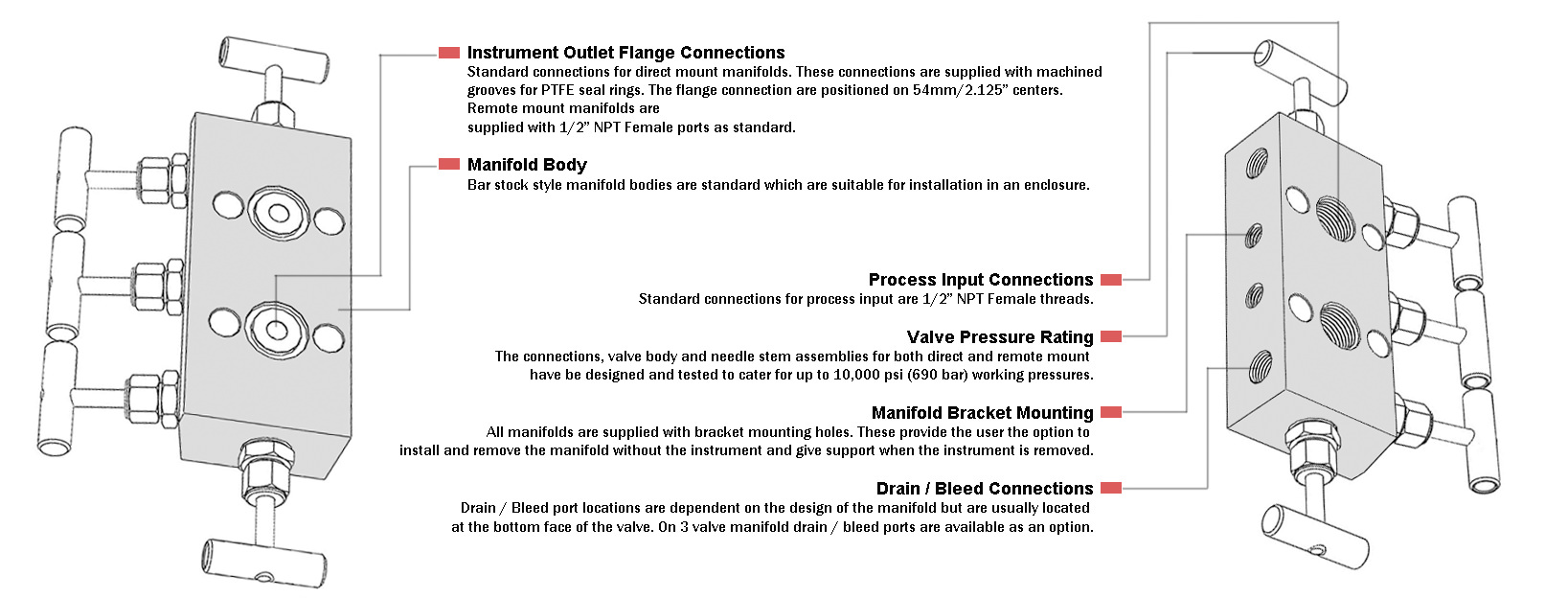
In essence, this kind of valve is fabricated as a monolithic device, featuring all three valves that are casted together into a single metallic block, which is attached to the pressure transmitter with O-ring seals, which often have a flanged face.
Bleed valves are, however, connected separately. They are often threaded into the transmitter’s chambers.
Refer to the image given below, which shows another version of a 3 valve manifold, connected to a differential pressure transmitter. Note the upper port on the diaphragm capsule; a bleed valve can be inserted into the port externally.
Generally, the two block valves are open so that fluid pressure can reach the differential transmitter. However, the equalizing valve is closed tightly to prevent the fluid from passing between the low and high pressure sides.
If the transmitter has to undergo maintenance, then it must be isolated first. This is done by shutting off the block vales and releasing the equalizing valve.
Valving a Differential Pressure Transmitter with 3 Valves Manifold into Service
A pressure transmitter manifold can be valved by performing the steps outlined below.
- Check and ensure that every valve is closed.
- Open the equalizing valves so as to ascertain that uniform pressure is applied on both sides of the transmitter manifold. This uniform pressure is formally referred to as zero differential pressure.
- Slowly turn on the higher pressure block valve. Inspect both sides of the transmitter and make sure there are no leakages.
- Now shut the equalizing valve such that pressure is locked on either side of the transmitter.
- Release the low pressure block valve to exert pressure on the low pressure side of the transmitter. Let the valve remain open until differential pressure has been established.
- The pressure transmitter manifold is now in operation.
In some instances, a bleed valve may be required, allowing trapped air to be released into the environment through the capsule housing.
Removing the Pressure Transmitter Manifold from Service
Perform the above steps in reverse order to remove the differential pressure transmitter from service. First shut the low pressure block valve. Now turn on the equalizing valve and then shut the high pressure valve.
The pressure transmitter manifold is inoperable now. Ensure that valves are opened and closed in the exact sequence presented here so as to ascertain two main things—that a high differential pressure isn’t reached when isolating the pressure transmitter manifold and that the inside fluid pressure is minimum before the transmitter is vented.
Even after being removed from service, the pressure will still be exerted on the capsule, which should then be decreased through bleeding. Thus, the last step is to open the bleed valve, which releases the trapped pressure inside the transmitter manifold.
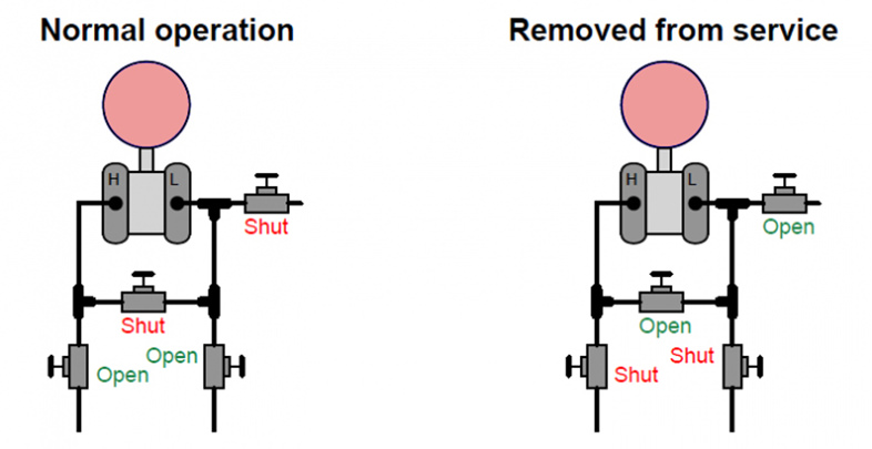
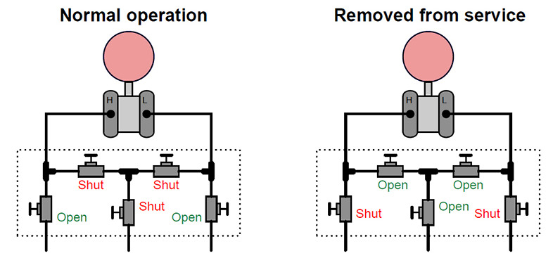
The illustrations below show the final valve positions when a transmitter is in service and when it has been removed.
5-Way Valve Manifold
In this type of pressure transmitter manifold, the bleed valve is built-in. Instead of venting out the pressure at the transmitter itself, this valve allows the trapped pressure to be passed through a tube and released at a remote location.
If the 5-way valve manifold is under normal operation, then both the low pressure and the high pressure valves are opened, whereas the other two valves are closed. Please ensure that the equalizing valve is never opened if both blocking valves are released.
Such a state can damage the pressure transmitter and manifold or even expose personnel to hazards if the fluid is too hot or of radioactive nature. Hence, a 5 valve pressure transmitter manifold is often to prevent situations of this sort.
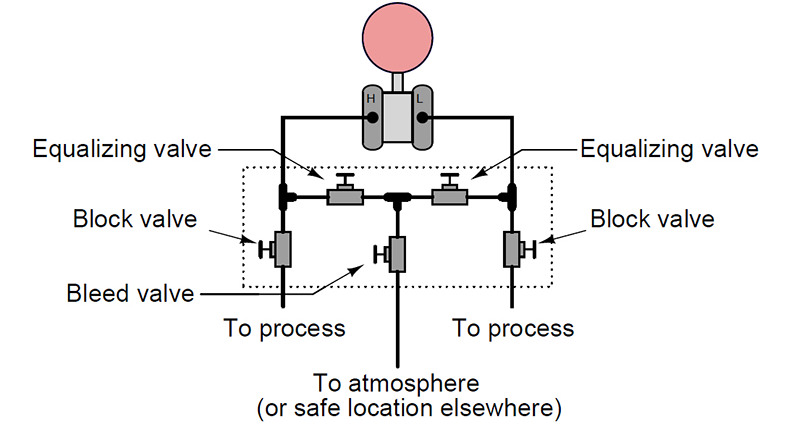
The block diagram of a 5 valve pressure transmitter is shown below.
Valving a Differential Pressure Transmitter with 5 Valves Manifold into Service
- Ensure that all five valves are closed.
- Open the equalizing valve first so that zero differential pressure is applied to both ends of the transmitter.
- Now turn on the high pressure valve slowly, simultaneously checking for potential leakages on both sides of the transmitter.
- Turn off the equalizing valve so as to lock pressure.
- Turn on the low pressure valve; this should establish a differential pressure.
- The transmitter is now said to be in service.
Removing a 5 Valve Manifold Transmitter from Service
Close both the low and the high pressure valves. Release the equalizing valve and then the bleed valve to emit process pressure into the environment.
The transmitter can now be said to be out of service. As in the case of a 3 valve manifold transmitter, the capsule will still be under pressure, which can be removed through bleeding.
The valve positions for both operational and nonoperational states are shown below.
Please bear in mind never to release the equalizing valve if both block valves are opened simultaneously.
If care is not exhibited, process fluid can reach the low and high pressure transmitter sides by passing through the equalizing valve. This can damage the transmitter and may even lead to human injuries.
If the tubes connecting the process and manifold are filled up with a fluid like glycerin or steamed water, it will be lost. Full fluids may be used for directing process water away from the impulse tubes.
2-Way Valve Manifolds
The 2-way valve pressure transmitter manifold works best for gauge pressure applications and it has single block-and-bleed configurations. The low pressure port is released into the atmosphere, whereas the high pressure port is connected to the device.
For removing the transmitter out of service, shut the blocking valve and release the bleed valve. This will vent out process pressure into the atmosphere.
The following image depicts eight pressure transmitters connected to each other. Seven of these feature a single capsule containing both the block and bleed valves, whereas the eighth transmitter (second transmitter from the left, located in the bottom row) comprises of a 5 valve manifold transmitter.
Study the figure carefully and note that a single bleed valve is attached to all the upper ports. Only the 5-valve transmitter is equipped with two bleed valves because it is the only device that can establish differential pressure. The rest of the transmitters are gauge pressure units, and hence, feature only a single bleed valve.
Operational Advice
When opening valves, back them off at least one quarter of a turn. This prevents seizing under normal operations and allows personnel to easily figure out the states of the valves.
A closed valve doesn’t turn easily because it is completely tightened in place, whereas an open valve can easily turn in either direction. However, closed valves shouldn’t be “backed off” because they must be secured tightly into place to remain in the shut-off position.