Transmitter Output Current Trim (Analog Trim)
The analog output current circuitry of a 4-20 mA transmitter is quite steady, so it is a rare occurrence when it drifts. In case the analog output current is incorrect; it’s possible to use current trim to correct the analog output signal. In case the analog output current is 4.13 mA, instead of the desired 4.00 mA, then it’s recommended to use current trim to adjust the current.
But what is it used for?
Current trim is used to match the transmitter analog output current to the current input of the analog input (AI) card channel on the DCS. If the transmitter shows 0.00% but the DCS reading states 0.13%, it’s easy to determine that the difference is because of disparity in current calibration. It might be because the DCS does not support current trim of channels in the AI and AO cards. If there is drift in the DCS input circuitry A/D conversion or D/A conversion and output circuitry, current trim must be performed in each device separately.
Current trim is only applicable to a transmitter with 4-20 mA analog output. It is valid for 4-20 mA/HART transmitters but not for FOUNDATION fieldbus (FF), PROFIBUS-PA, or WirelessHART transmitters. The discrepancy exists because pure digital transmitters have no 4-20 mA analog output.
The technician needs to measure the physical output current from the transmitter in order to get an appropriate reading for current trim. Therefore, it is required that the technician either does current trim in the field at the process location by connecting a multimeter to the transmitter test terminals or bring back the transmitter into the workshop to perform current trim. If the former option is chosen, the technician will require a handheld communicator.
Trim Quick Reference
The table given below summarizes the difference between sensor trim, range setting, and current trim.
| TASK | LOCAL CENTRAL | EXAMPLE | 4-20mA-HART | FOUNDATION Fieldbus | PROFIBUS |
| Sensor Trim | Local | Correct the sensor reading to applied input. For instance: if pressure is 0 bar but transmitter reading is 0.03 bar, then sensor trim is used adjust it to 0 bar | YES | YES | YES |
| Range Setting | Local or Central | Set the 4mA and 20mA points, For instance, set range of pressure transmitter to get 4-mA when input is 0-bar and 20mA when pressure is 40bar. | YES | NO* | NO* |
| Current Trim | Local | Correct the analog output current. For instance, if the analog output current is 4.13mA when it should be 4mA, then current trim is used to adjust it to 4mA. | YES | No | No |
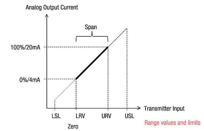
Range Values and Limit Summary
The table given below summarizes the relationship between range values and limits.
| LSV | Lower Sensor Limit | Lowest possible value for the 4mA point |
| LRV | Lower Range Value | The 4mA point |
| URV | Upper Range Value | The 20mA point |
| USL | Upper Sensor Limit | Highest possible value for the 20mA point |
| Span | URV minus LRV | |
| Zero | Same as LRV | |
| Turndown | Span divided by URV |
Valve Positioner Setpoint Current Trim
Just like in the case of analog output current circuitry, it is rare for the setpoint input current circuitry of a 4-20 mA positioner to vary and drift. Even if it does drift, there is always a reason behind this discrepancy. If the input current sensing is incorrect, it’s possible to use current trim to correct the input signal. For example, if the current input reads 4.13 mA instead of the desired reading of 4.00 mA, current trim should be used to adjust it so that the setpoint reads correctly.
Current trim is used for matching the positioner current input to the analog output current of the analog output (AO) card channel on the DCS. For example, if the DCS PID output is 0.00%, it’s possible that the positioner setpoint shows 0.13% because of the disparity in current calibration.
Positioners with 4-20 mA input are the only ones that current trim is applicable for. It is valid for 4-20 mA/HART positioners, but not for FOUNDATION fieldbus (FF) positioners. The discrepancy exists because pure digital positioners have no 4-20 mA input.
In order to get an accurate current trim, the technician is required to connect a precision current source. This value can also be obtained by measuring the physical input to the positioner. Hence, it is important that the technician either does current trim in the field or bring the valve back into the workshop to perform current trim. If they decide on the former, they’d have to use a handheld communicator to get current trim in the field.
Valve Positioner Travel Stroking (Position Feedback Sensor Trim)
In order to find a valve positioner’s fully opened and fully closed positions, stroking is used. This is an automated procedure that trims (calibrates) the position transmitter feedback sensor. Simply put, it is just like a sensor trim for a pressure or temperature transmitter. Here, however, a known reference isn’t required. The positioner automatically stokes the valve over its full travel in order to discover the open and closed end-positions.
Similarly, the analog 4-20 mA actual valve position feedback current output of a 4-20 mA positioner is calibrated in the same way that a 4-20 mA transmitter is trimmed. It’s important to note here that the process is not required for FOUNDATION fieldbus positioners or for position feedback transmitters that are based on WirelessHART.
Sensor Trim Procedure
Plants utilize a mix of transmitters to cater to different measurement needs. These devices are from different manufacturers and so deviations in measurements are expected. It’s a fact that all sensors drift, so at some point in time, all sensors need a trim to ensure accurate measurement. However, the procedure for calibration depends on the type of transmitter being used:
- Pressure transmitter: Apply pressure from the calibrator or dead weight tester for calibration. Equalize the manifold for zero trim.
- Temperature transmitter: Use calibrator or resistance decade box to apply milli-voltage or resistance.
- Flowmeter: Must be calibrated against prover or master meter.
- Valve position transmitter: Stroke the valve fully opened and fully closed.
- pH transmitter: Test the pH sensor in buffer solutions.
Just like calibration, the procedure for sensor trim may also vary slightly from one manufacturer to another. The discrepancy depends on the requirement for the sensor technology being used. There are some incidences when calibration is easier in the workshop. Take pH sensor buffering for example. In order to complete the process, the pH sensor has to be put in buffer solutions and distilled water to increase convenience; this can easily be carried out in the lab. With the development of smart pH sensors, the process has become even simpler. These sensors have a memory chip inside, which enables calibration in the lab, then transporting the sensors into the field, carrying the calibration offset and slope data inside its memory chip. Once it is connected, the pH transmitter/analyzers easily upload the calibration data from the sensor memory, thus increasing convenience.
Sensor Zero Trim Calibration
Typical steps in a sensor zero trim calibration for a pressure transmitter are as follows. (Assume HART operating from Remote System)
- Instruct the technician to inform operations about putting the associated control loop in manual. This ensures that the control is not upset when PV changes as the change in sensor readings also occur.
- Inform the technician about the expected changes in the sensor reading.
- Instruct the technician to apply zero physical input (e.g., by isolating, equalizing, and venting the manifold).
- Instruct the technician to wait and observe as the sensor reading stabilizes and the transmitter corrects it.
- Inform the technician that the zero sensor trim was successful.
- Instruct the technician to inform operations to put back the associated control loop in automatic.
Find out: HART Protocol EST4300 Smart Pressure Transmitter in our Shop
You may also interest in:
- How 4-20mA Transmitter Works
- Capacitance Differential Pressure Transmitter Working Principle
- DP Transmitters Applications
- Fieldbus, ProfiBus and HART Protocols
- Some Important Transmitter Calibration Terms You Need to Know
- Sensor Trim – Smart Transmitter Calibration Tutorial Part 1
- Range Setting – Smart Transmitter Calibration Tutorial Part 2