Introduction
You can carry out calibration through a handheld communicator in the field, a laptop on the bench in the workshop, or an intelligent device management (IDM) software.
Device manufacturers use Electronic Device Description Language (EDDL) to set the format that the system uses to display device information and functions to technicians.
It is because of the technology that calibration of smart transmitters and other intelligent devices has become easier in recent times.
With the help of this tutorial, understanding the common principles of calibration, re-ranging, and trimming becomes easier.
Since the same principles also apply to various kinds of transmitters, it pays off to understand the factors that differentiate them.
As the measurement done, sensing principle, and manufacturer varies, the detailed procedure also experiences some changes.
Calibration
According to the definition, the term “calibrate” can mean several things:
- Set the range (scale)
- Trim (correct) the sensor (transducer) reading against a standard
- Compare the sensor (transducer) reading to a standard output and observe the maximum level of error without correcting (trimming) it.
This step is often done in five points, increasing and decreasing. To know for sure if the transmitter is trimmed or not, take a look at the error readings. If the error is consistently too high, the transmitter may be trimmed or replaced.
ANSI/ISA–51.1 Definition of Terms
Calibrate: To ascertain the output of a device corresponding to a series of values of the quantity which the device is to measure, receive, or transmit.
The data obtained can be used to:
- Determine the sites where scale graduations must be placed;
- Adjust the output and regulate it to a value within the specified tolerance;
- Ascertain the error by comparing the device output reading against a standard.
Calibrating Smart Transmitters
The term ‘calibration’ is a misunderstood word that is often taken out of context, especially when talking about smart transmitters. When analog transmitters were used predominately, calibration was understood under a different context.
It referred to applying a physical input and using the trim potentiometers to adjust the transmitter. This step allowed the analog output current to come close to the desired measurement range.
It wasn’t until the smart transmitters appeared that the “calibration” process was categorized into three parts:
- Sensor trim
- Range setting (re-ranging)
- Current trim
There’s a valid reason for separating these functions. With the introduction of smart transmitters, there is no need to apply physical input when changing the range. This change has been time and cost effective and is the real reason behind the rapid success of smart transmitters.
It’s important to understand that “sensor trim” and “range setting” are two different concepts. Even though both of them are a part of calibration, their definition varies and so does their function. The popular opinion is that range setting is closer to the definition of configuration than calibration.
Sensor Trim (Digital Trim)
All sensors tend to drift over time and the reasons can vary. The changes might occur because of extreme pressure or temperature, vibration, material fatigue or contamination. There are several other factors that can have an impact on the sensor reading such as the mounting position.
Sensor trim is useful in correcting the digital reading visible on the device’s local indicator LCD, which is received through digital communication. For instance, if the pressure is 0 bar but the transmitter reading shows 0.03 bar, the sensor trim will be used to adjust it back to 0 bar.
Sensor trim is also useful in optimizing performance over a smaller range than was originally trimmed in the factory.
The basic principle for calibration (sensor trim) of all transmitters follows the same pattern;
- Apply a known input
- Inform the transmitter what it is
- The transmitter calculates internal correction factors
- The transmitter uses these new factors to compute a new correct measurement reading.
The technician needs to apply a physical input to the transmitter for sensor trim. Therefore, it’s essential they do sensor trim in the field at the process location. In case that option isn’t viable, the transmitter needs to be brought back into the workshop to perform sensor trim.
This applies to 4-20 mA/HART, WirelessHART, FOUNDATION fieldbus, as well as PROFIBUS transmitters. The easiest way to do sensor trim in the field is by using a handheld communicator connected to the running bus, which is supported by 4-20 mA/HART, WirelessHART, and FOUNDATION fieldbus.
For PROFIBUS-PA, however, there are two ways to perform sensor trim. Sending the trim command from the control system or temporarily disconnecting the transmitter from the running bus.
Typically, there are three forms of sensor trim:
- Zero sensor trim
- Lower sensor trim
- Upper sensor trim
Zero trim requires the physical input applied to be zero. This form of sensor trim is often used with pressure transmitters for best accuracy. Lower and upper sensor trims are used to find out the sensor trim in two points, close to lower range value and upper range value.
In order to perform the sensor trim, a known physical input is applied to the transmitter. The technician enters the applied value (on a computer or handheld communicator), which allows the transmitter to correct itself.
The transmitter stores the physical input values applied for lower and upper sensor trim, which are referred to as Lower Sensor Trim Point and Upper Sensor Trim Point respectively.
To perform an accurate sensor trim, precise input has to be applied. This can be done with the help of the factory calibration equipment, which is usually more accurate than the portable calibrators at site.
Since the transmitters in current use are typically very stable, sensor trim of brand new transmitters is rarely done at the time of commissioning.
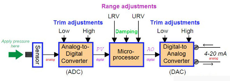
It’s important to note that sensor trim is not done in the sensor itself but in the firmware of the transmitter microprocessor. The trim is a mathematical function that adjusts numerical bias and gain factors. It is the sensor reading after the A/D conversion that is trimmed, not the sensor hardware.
Sensor trim is the aspect of calibration, which this article focuses on. That is:
- Level calibration
- Flow calibration
- Pressure calibration
- Temperature calibration, etc.
Sensor Trim Points
The purpose of the (CAL_POINT) parameters is to tell the location of the pints where sensor trim was last performed and to start the process again, if required. If the sensor trim reading parameters are 0 and 360 mbar, it means these are the points at which it was calibrated.
Since the transmitter extrapolates after the reading, it might not provide accurate readings for measurements ranging from -600 to +600. This is not uncommon, so you can make do with these measurements. It is possible to achieve greater accuracy if sensor trim is performed at -600 and +600.
It’s important to note that since sensor trim points are NOT range configuration parameters they cannot be ‘set’. Configuration parameters are written when sensor trim is performed.
The transmitter then remembers these points where the trim was made. Usually, there is a sensor trim wizard (“method”) that guides the technician through the calibration process step by step. The sensor trim wizard is also the technology that writes the sensor trim point parameters.
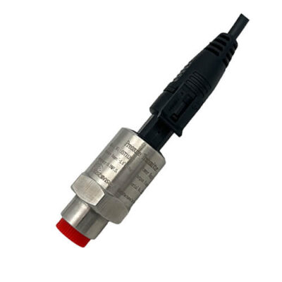
Find out: HART Protocol EST4300 Smart Pressure Transmitter in our Shop
You may also interest in: