When you’re selecting instrumentation for your process control system, few decisions matter more than choosing the right pressure transmitter. The 4-20mA signalstandard has dominated industrial automation for decades, and understanding why—and how to leverage it properly—can make the difference between a reliable system and one plagued by measurement errors and downtime.
Let me walk you through everything you need to know about 4-20mA pressure transmitters, from the fundamentals to advanced selection criteria that most guides don’t cover.
Why 4-20mA Became the Industry Standard
Back in the 1950s, process industries faced a problem: how to transmit sensor data over long distances without significant signal degradation. Voltage signals dropped off quickly due to wire resistance. The solution? Current loops.
Current remains constant throughout a series circuit regardless of wire resistance. This simple physics principle revolutionized industrial instrumentation. The 4-20mA range wasn’t arbitrary—4mA provides a “live zero” that distinguishes between a zero reading and a broken wire, while 20mA offers sufficient range without excessive power consumption.
Today, despite digital protocols gaining ground, 4-20mA remains the backbone of process control because it’s simple, reliable, and universally compatible.
How 4-20mA Pressure Transmitters Actually Work
A 4-20mA pressure transmitter contains three essential components working together:
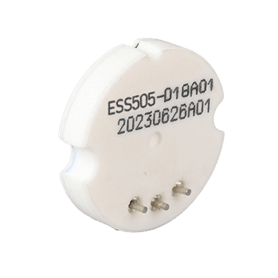
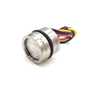
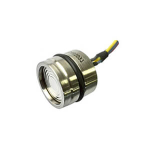
The sensing element converts pressure into a mechanical deflection or electrical change. This might be a piezoresistive silicon diaphragm, a capacitive ceramic cell, or a strain gauge assembly. Each technology has distinct advantages depending on your application.
The signal conditioning circuit amplifies and linearizes the sensor output, compensates for temperature effects, and converts it to a proportional current signal.
The current loop driver regulates output current precisely between 4 and 20mA, drawing power from the same two wires that carry the signal.
| Specification | What It Really Means | Typical Values |
|---|---|---|
| Accuracy | Maximum deviation from true pressure across the calibrated range | ±0.075% to ±0.5% of span |
| Stability | How much the calibration drifts over time | ±0.1% to ±0.25% per year |
| Response Time | How quickly output reaches 90% of final value after pressure change | 50ms to 500ms |
| Temperature Effect | Additional error per degree of ambient temperature change | ±0.01% to ±0.05% per °C |
| Pressure Range | Minimum and maximum pressures the sensor can measure | -1 bar to 10,000 bar |
| Overpressure Rating | Maximum pressure before permanent damage | 2x to 10x full scale |
Accuracy gets marketed heavily, but don’t obsess over the last tenth of a percent unless your process genuinely requires it. A 0.1% transmitter costs significantly more than a 0.25% unit, yet many applications function perfectly well with the latter.
Stability matters more than most engineers realize. A transmitter might be accurate when installed, but if it drifts 0.5% annually, you’re recalibrating constantly. Look for proven long-term stability, especially in applications where recalibration is difficult or expensive.
|
Not sure which accuracy class your application needs? Our application engineers review your process requirements and recommend the most cost-effective solution. Request application review →
|
4-20mA Pressure Transmitter Basics
A sensor is an input device that provides a usable output in response to the input measurand. A sensor is also commonly called a sensing element, primary sensor, or primary detector. The measurand is the physical parameter to be measured.
An input transducer produces an electrical output that is representative of the input measurand. Its output is conditioned and ready for use by the receiving electronics like PLC or DCS.
The receiving electronics can be an indicator, controller, computer, PLC, DCS etc. The term “transmitter,” as commonly used with industrial process control instrumentation, has a more narrow definition than those of a sensor or transducer:
A transmitter is a transducer that responds to a measured variable by means of a sensing element and converts it to a standardized transmission signal (like 4-20mA) that is a function only of the measured variable.
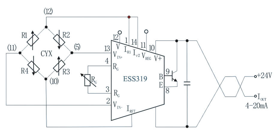
Transmitters can have any of several electrical connection schemes. The most common and easiest to use is the two-wire, loop-powered configuration. This is generally the basic configuration for industrial process control systems when digital communication is not required.
As shown in Below Figure, only two wires are used to accommodate both power to the transmitter and output signal from the transmitter.
To facilitate a closed-loop control system, information from the process must be obtained before a controller can determine what action may be required by a control element. Some popular names for the sensing devices that provide the information are sensors, transducers, and/or transmitters.
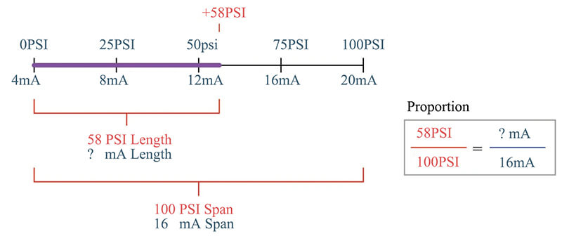
The standard loop current is usually 4 to 20 mA. Important calibration parameters with a current loop are Zero, full scale, and span. With the 4- to 20mA range, the loop current is normally 4 mA when the measurand or Process Variable is at zero, and 20 mA when the measurand or Process Variable is at full scale.
The difference between Zero and full scale, 16 mA, is called the span. Thus, the span corresponds to the indicated range of the measurand or Process Variable.
When considering a flow transmitter, for example, the range of the measurand or Process Variable is 0.0 to 100.0 m3/hr, corresponding to a 4- to 20-mA loop current (output span is then 16 mA); the output scaling factor is 0.16 mA/(m3/hr) (which is 100 m3/hr 16 mA).
4-20mA Pressure Transmitters Working Animation
Assumptions : Standard +24V DC with 20mA
In General PLC / DCS Analog Input card channel supplies more than 20mA current to power the loop.
Case 1 : Process Variable @ 0%
The PLC / DCS Analog Input card transmits a standard +24 V DC, 20 mA signal to Power the Transmitter.
A one pair cable is used to power the transmitter and the same cable is used to receive the data in the 4-20mA current range.
Transmitter receives +24V DC, more than 20mA signal in the loop. A minimum +5V DC, 20mA signal is required to proper functioning of transmitter. In Practical there will be a voltage drop in the loop.
Transmitter have an inbuilt voltage regulator function which is used to regulate the loop current. The Transmitter will be configured with LRV, URV and other details of Process variable. The loop current will be varied / changed by the transmitter as per the measured Process variable.
The 4-20mA current will be converted into standard 1 – 5 V DC using a precision 250 ohms resistor. The Analog to Digital converter will be used to convert the voltage into digital signal which is used to indicate the Process Variable value in the DCS / PLC HMI.
Example: A Flow Transmitter with a range of 0 to 100 m3/hr. Transmitter indicates 0 m3/hr as there is no flow in the line. DCS / PLC powers the transmitter with +24V DC, 20mA.
As Process Variable is 0 m3/hr, the transmitter regulates the loop current to 4mA and its equivalent voltage is 1 V DC which is measured by A/D Converter which indicates 0% of Process Variable.
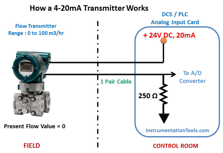
Note: The loop current will be same either at starting or end or any point in the loop. For easy understanding only, both 20mA & 4 mA signals are shown in the animation. In Practical, When we measure the current at any point in the loop, the transmitter output current will be found i.e. 4mA as per above figure, so just assume DCS/PLC system powers the loop with +24V DC, 20mA (generally systems supplies more than 20mA) while transmitter regulates the loop current within 4mA to 20mA as per its configuration & real time process variable value. If you want to measure the PLC/DCS loop power i.e. 20mA (as per above figure) signal then disconnect the transmitter from the loop & Connect the multimeter in series to measure the loop current. And the one pair cable is a twisted pair cable.
Case 2: Process Variable @ 50%
Same Principle applies. The Transmitter adjust the loop current as per the Process Variable.
The only difference is the transmitter sensing element changes its output as process variable varied from 0% to 50%. The transmitter regulates the loop current as per the sensing element.
Example: Process variable indicates 50 m3/hr. Transmitter regulates output to 12mA in the loop as per the configured range and measured process variable and its equivalent voltage is 3 V DC which is measured by A/D Converter which indicates 50% of Process Variable.

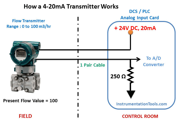
Case 3 : Process Variable @ 100%
Same Principle applies. The Transmitter adjust the loop current as per the Process Variable.
The only difference is the transmitter sensing element changes its output as process variable varied from 50% to 100%. The transmitter regulates the loop current as per the sensing element.
Example: Process variable indicates 100 m3/hr. Transmitter regulates outputs to 20mA in the loop as per the configured range and measured process variable and its equivalent voltage is 5 V DC which is measured by A/D Converter which indicates 100% of Process Variable.
Measured or Process Variables
Although almost any type of transducer can be configured as a transmitter, the most common types for industrial process control comprise measurands or Process Variables like temperature, pressure, flow, level etc.
Transmitters for measuring other parameters will have the same possibilities for connection and communication methods, with the main differences being in the sensing element design of transmitter and electronic equipment will be same with slightly software modification.
Two Wire Loops
The main advantage of a two-wire loop is that it minimizes the number of wires needed to run both power and signal. The use of a current loop to send the signal also has the advantages of reduced sensitivity to electrical noise and to loading effects.
The electrical noise is reduced because the two wires are run as a twisted pair, ensuring that each of the two wires receives the same vector of energy from noise sources, such as electro- magnetic fields due to a changing current in a nearby conductor or electric motor.
Since the receiving electronics connected to the transmitter is designed to ignore common-mode signals, the resulting common-mode electrical noise is ignored. The sensitivity to loading effects is reduced because the current in the twisted pair is not affected by the added resistance of long cable runs.
A long cable or other series resistance will cause a greater voltage drop but does not affect the current level as long as enough voltage compliance is available in the circuit to supply the signal current.
The circuit compliance to handle a given voltage drop from additional loop devices depends on the transmitter output circuit and on the power supply voltage. The typical power supply for industrial transmitters is +24 VDC.
If 6 volts, for example, are needed to power the transmitter and its output circuit, then 18 volts of compliance remain to allow for wire resistance, load resistance, voltage drops across intrinsic safety (IS) barriers and remote displays, etc.
Where the current loop signal is connected to the main receiving equipment (PLC/DCS) or data acquisition system, a precision load resistor of 250 ohms is normally connected. This converts the 4 to 20 mA current signal into a 1 to 5 volt signal, since it is standard practice to configure the analog-to-digital converter of the receiving equipment (PLC/DCS) as a voltage-sensing input.
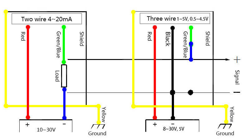
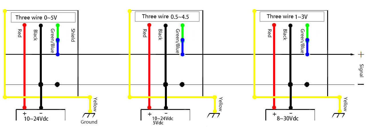
Three and Four Wire Loops
In contrast to the two-wire current-loop configuration, some current-loop devices require a three or four wire connections. These are not loop powered and therefore have a separate means for providing power by adding one or two more wires.
In a four-wire configuration, the current-loop wires can be a twisted pair, and the power supply wires a separate twisted pair. This preserves the ability to reject electrical and magnetic common-mode interference. This is not so effective in a three-wire configuration due to the common connection for the return current path.
Typically, though, when an instrumentation engineer specifies a current-loop transmitter for industrial process control, it is assumed that a two-wire, loop-powered 4 to 20 mA device is intended.
Other data signals may also be impressed upon the same wire pair, or alternatively, various digital communication techniques can be used instead of a current loop, if required.
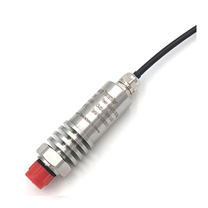
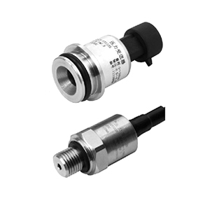
Check details: 4-20mA Pressure Sensor
Two-Wire vs. Four-Wire: When It Matters
Standard 4-20mA transmitters use two-wire configuration—signal and power share the same conductors. This simplicity reduces installation costs and works perfectly for most applications.
Four-wire transmitters separate power (two wires) from signal (two wires). You gain higher accuracy potential because the signal circuit doesn’t share current with the transmitter’s power consumption, eliminating a small but sometimes significant error source.
Choose four-wire when: you need the absolute highest accuracy, you’re already running four-wire cable for other reasons, or you’re measuring very small pressure differentials where every hundredth of a percent matters.
For 95% of applications, two-wire is the right choice. It’s simpler, cheaper to install, and plenty accurate.
Final Thoughts
The 4-20mA pressure transmitter represents decades of refinement in industrial instrumentation. It’s survived because it works—reliably, day after day, in environments from arctic pipelines to desert refineries. Understanding the fundamentals I’ve covered here helps you specify transmitters that perform well in your specific application rather than just looking good in a datasheet.
Your pressure measurement system is only as good as your weakest component. Choose wisely, install carefully, and maintain appropriately. The difference between a successful installation and a problematic one often comes down to attention to these details.
Need help specifying the right transmitter for your application? Our engineering team has helped hundreds of companies optimize their pressure measurement systems. We’re here to ensure you get exactly the solution your process needs.