J1939 Pressure Sensor-The Definitive Guide

J1939 Pressure Sensor-The Definitive Guide

What is a J1939 Pressure Sensor?

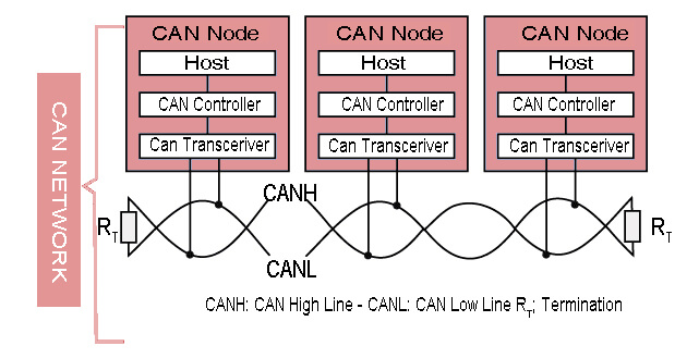
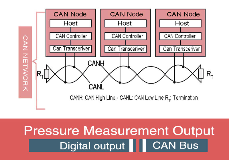
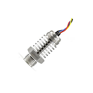
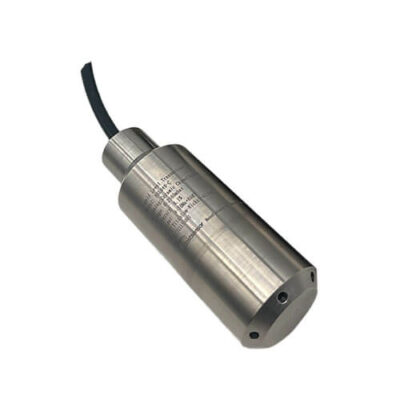
A J1939 pressure sensor is a transducer that converts physical pressure (hydraulic, pneumatic, or gaseous) into a digital packet that follows the SAE J1939 protocol and is broadcast on a Controller Area Network (CAN-Bus). In practice it combines three functional blocks

BlockPurposeTypical Components
Sensing elementConverts pressure → millivolt signalPiezoresistive, thin-film, ceramic capacitive
Signal conditioningAmplifies & linearisesInstrumentation amplifier, temperature-compensation network
J1939 nodeFormats data into J1939 Parameter Group Number (PGN) frames and handles bus accessCAN controller + microcontroller + J1939 stack

Key characteristics that separate a J1939 pressure sensor from “plain” CAN sensors:

  • Hard-coded PGNs – most vendors map pressure to PGN 65266, SPN 108 (Hydraulic Pressure) or custom proprietary PGNs.
  • 29-bit extended identifiers – required by J1939.
  • Network management – supports address claiming, diagnostics (DM1/DM2), and transport protocol for >8-byte data.
  • Vehicle/industrial vocabulary – interpretable by ECUs made by John Deere, Caterpillar, Volvo, etc.

In short, whenever you need a plug-and-play pressure reading that any J1939-aware ECU or data logger can “understand” without custom parsing, you need a J1939 pressure sensor.

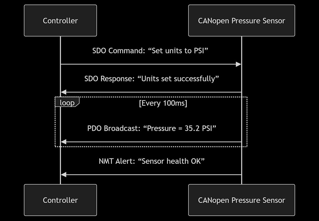
CAN-Bus vs CANopen vs J1939 – How Do They Relate?

All three acronyms sit on different layers of the same communication cake. The table below highlights where each belongs:

ISO/OSI LayerCAN-Bus (ISO 11898)CANopen (CiA 301)J1939 (SAE J1939-21/71/73 etc.)
PhysicalTwisted pair, 1 Mbit/s max, dominant/recessive bitsinherits CANinherits CAN
Data-LinkArbitration, 11/29-bit IDs, CRC, ACKinherits CANinherits CAN
Network— (none)NMT (Node-State)Address Claiming (BAM/RTR)
Transport— (none)SDO, PDOTP.BAM, TP.CM
Application— (none)Device Profiles (CiA 406 Pressure/Force)Vehicle/Pgn-SPN dictionary (pressure = SPN 108 etc.)

Let’s make a comparison:

  1. CAN-Bus is only Layer 1/2: bit timing, arbitration, and error handling. Frames are meaningless unless an upper-layer protocol defines what each identifier means.
  2. CANopen adds a standardised object dictionary, heartbeat, and emergency messages. IDs are primarily 11-bit; node ID is encoded inside the base identifier. It is popular in factory automation, medical devices, and renewable energy.
  3. J1939 targets diesel powertrains, off-highway machinery, and heavy EVs. It mandates 29-bit identifiers and reserves specific PGNs for pressure, temperature, RPM, etc. J1939 also defines diagnostic messages (DM1-DM14) and transport protocol for multi-packet data.

Why this matters when you select a pressure sensor

ScenarioBest ChoiceReason
You have mixed ECUs from Caterpillar, Cummins, or DeutzJ1939 sensorEvery ECU already listens for pressure PGNs
You integrate into a factory robot with CiA 406 masterCANopen sensorMaster polls/receives via PDO 0x180+NodeID
You build your own microcontroller board, no upper-layer stackRaw CAN sensorGives you full freedom, cheapest silicon

Remember: all J1939 and CANopen devices are CAN devices, but not all CAN devices speak CANopen or J1939. Selecting wrongly forces you to write glue code or gateway firmware.

How Does the J1939 Protocol Work?

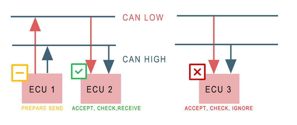
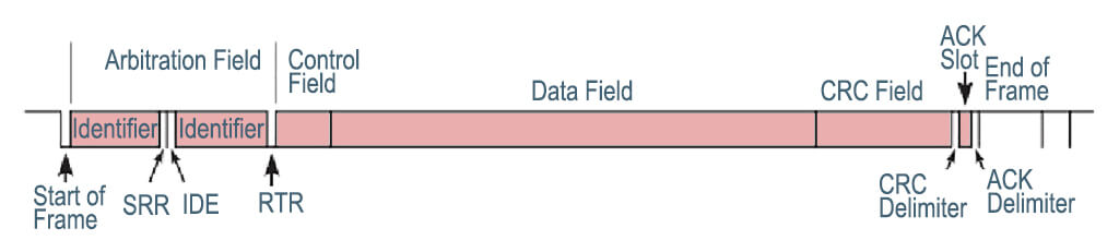
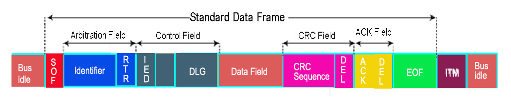
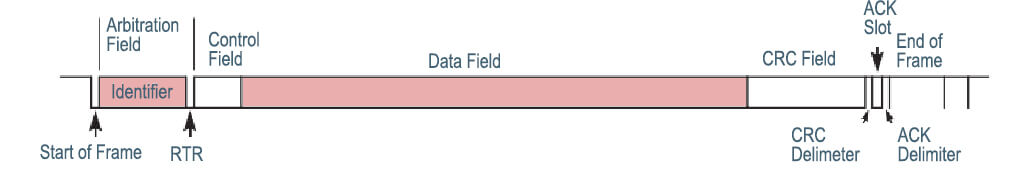
  1. Identifier Structure (29 bit)
    Priority (3) | Reserved (1) | Data Page (1) | PDU Format (8) | PDU Specific (8) | Source Address (8)
    • PGN = DP + PF + PS (or DP + PF when PF < 240).
  2. Pressure Example
    • PGN 65266 (0xFEEE) “Analog Pressure #1” contains SPNs: 108 (Hydraulic Pressure), 109 (Air Pressure), etc.
    • A sensor microcontroller fills the 8-byte data field with scaled values (e.g., 1 bit = 0.5 kPa, offset = 0 kPa).
  3. Address Claiming
    On power-up each node sends CLAIM (PGN 60928). If an address conflict occurs, the node with lower NAME priority keeps the address; the loser must pick another or go silent. High-end sensors allow changing the preferred address via over-the-bus commands.
  4. Transport Protocol
    For payloads >8 bytes (e.g., calibration curves) the sensor uses TP.BAM (broadcast) or TP.CM/TP.DT (peer-to-peer) splitting data into up to 255 packets.
  5. Diagnostics
    DM1: Active DTCs → flashing MIL on dashboards.
    DM2: Previously active DTCs.
    A quality pressure sensor sets DM1 bits for over-range, internal fault, EEPROM error, etc., enabling predictive maintenance.
  6. Update Rate and Bus Loading
    Standard broadcast rate for pressure PGNs is 100 ms (10 Hz). At 250 kbit/s this uses <1 % of bus bandwidth, leaving headroom for dozens of sensors plus chatter from the engine ECU.

Understanding the above lets you estimate bus utilisation, address planning, and diagnostics strategy before you purchase hardware.

Why / When Do You Need a J1939 Pressure Sensor?

Use J1939 when your project ticks at least two of the boxes below

RequirementJ1939 FitHow the Sensor Helps
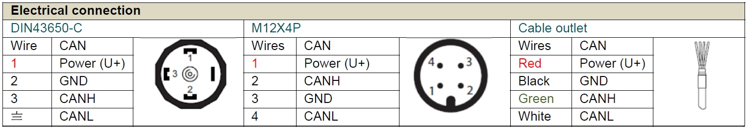
Existing J1939 backbone (trucks, harvesters, large AGVs)ExcellentSensor drops in with one Deutsch DT04-4P connector—zero code
Distance >5 m between sensor & ECUGoodDigital data immune to voltage drop & EMI; no 4-20 mA errors
Multi-vendor ecosystemExcellentCommon PGN definitions avoid proprietary decoding
Strict uptime & diagnosticsExcellentDM1/DM2 messages flag out-of-tolerance before breakdown
Need to log data to telematics gatewayGoodGateways (Raven, Trimble, Mobileye) already parse pressure PGNs
Cost-sensitive, single-vendorFairJ1939 stack adds ~5 USD BoM vs. analog; CANopen might be cheaper
Update speed >100 HzPoorJ1939 typical 10–20 Hz; choose analog or raw CAN

Typical applications:

  1. Hydraulic brake and suspension control on heavy trucks.
  2. Boom pressure monitoring on concrete pumps or aerial platforms.
  3. Hydrogen storage pressure in fuel-cell buses (with 500 bar range).
  4. Transmission oil pressure diagnostics to schedule predictive maintenance.

Business benefits:

  • Wiring savings – a single 4-wire trunk replaces multiple shielded analog lines.
  • Simpler safety certification – error flags are digital (no ambiguous 3.5 mA fault).
  • Fleet-wide compatibility – one SKU covers John Deere, Case-IH, Komatsu.

Summary

A J1939 pressure sensor is the fastest route to obtain reliable, diagnostics-rich pressure data on any heavy-duty CAN network. Understanding how CAN-Bus, CANopen, and J1939 stack together lets you choose the right sensor before design freeze. Evaluate your bus architecture, diagnostics needs, and vendor mix; if they align with J1939, the small price premium buys plug-and-play integration, less wiring, and fleet-wide interoperability. For additional questions, revisit the FAQ or contact a sensor vendor that offers configurable PGNs and robust self-diagnostics.

FAQ

Can I change the PGN or source address myself?

Most quality sensors support proprietary PGN 0xEF00 “Configure”. Using a CAN tool send a “Set SA” command, cycle power, and the new address is stored in EEPROM.

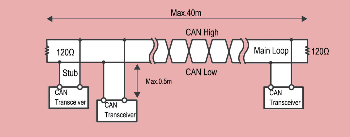
What cable length is safe at 250 kbit/s?

Up to 40 m with 24 AWG twisted pair and ≤120 Ω termination. If you need 500 kbit/s keep it under 30 m or use repeaters.

How is the pressure value scaled?

The J1939 standard for SPN 108 uses: Resolution = 0.5 kPa/bit, Offset = 0 kPa, Data Type = uint16. So 0x07D0 = 2000 kPa.

Can one ECU handle both CANopen and J1939 sensors?

Yes, if it has two CAN ports or a software stack that can filter by identifier range. Keep them on separate buses to avoid ID collisions.

What happens if the sensor fails self-test?

It transmits DM1 with SPN 108 FMI (5) “Current Below Normal”. Many dashboards will light a red lamp within 250 ms.

Is there a cybersecurity concern?

Basic J1939 has no encryption. For road vehicles in UNECE R155 scope you must add a secure gateway or migrate to J1939-22 (CAN-FD + SecOC).

Analog vs J1939 price delta?

Typical OEM volume (1 000 pcs) ex-works prices: 4-20 mA = 23 USD, J1939 = 28–30 USD. The 5-7 USD premium often pays back in harness savings and diagnostics.

CANOpen Pressure Sensor

CANOpen Pressure Sensor

Think of your car (or a complex machine) as a bustling party. You’ve got:

  • The Engine (the life of the party, maybe a bit loud)
  • The Brakes (serious and safety-conscious)
  • The Airbags (hopefully quiet, but ready for action)
  • The Dashboard (trying to keep track of everything)
  • Sensors Everywhere! (Temperature sensors, speed sensors, pressure sensors – the wallflowers quietly observing)

Now, all these “guests” need to talk to each other quickly and reliably. “Engine, you’re getting too hot!” “Brakes, I’m applying pressure now!” “Dashboard, show the driver the tire pressure!”

This is where CAN Bus and CAN Open pressure sensor comes in.

CAN Bus: The Party Line Phone System

What it is CAN Bus

CAN (Controller Area Network) is a powerful serial bus system for a fast data exchange between electronic control units (ECUs). It has a multi-master functionality so that all CAN nodes send data and different CAN nodes can poll the bus simultaneously.

It was developed by Robert Bosch GmbH in 1983, initially for automotive technology. In addition to pas­senger cars and com­mercial vehicles, CAN networks are increas­ingly used in ships, trains and airplanes as well as in auto­mation tech­nol­ogy and mechanical engineering. Today almost all micro­controllers are equip­ped with a CAN interface.

CAN stands for Controller Area Network. Think of it as the simple, sturdy telephone line installed throughout the entire car (or machine).

How it works

Instead of each guest having a separate phone line to every other guest (messy and expensive!), everyone connects to this one main line – the CAN Bus (usually just two wires twisted together!).

CAN Network For Data Transmission

The Rules

It has very strict rules:

  • Only one guest talks at a time. (No shouting over each other!).
  • Everyone listens constantly. Even if it’s not addressed to them specifically, they hear everything.
  • Messages are short and to the point. “Engine Temp: 95°C”, “Brake Pressure: 45 Bar”.
  • It’s super tough. Designed for noisy environments (like under your hood!) – if one message gets garbled, it just sends it again. Safety first!

CANbus The Machine Communication Highway

The Benefit of Can Bus

It’s a cheap, robust way for lots of components to share information without a tangled mess of wires.

CAN BUS-es

  • Simple & low cost
  • ECUs communicate via a single CAN system instead of via direct complex analogue signal lines -reducing errors, weight, wiring and costs
  • Fully centralized
  • The CAN bus provides ‘one point-of-entry’ to communicate with all network ECUs – enabling central diagnostics, data logging and configuration.
  • Extremely robust
  • The system is robust towards electric disturbances and electromagnetic interference – ideal for safety critical applications (e.g. vehicles)
  • Efficient
  • CAN frames are prioritized by ID so that top priority data gets immediate bus access, without causing interruption of other frames

Popular CAN bus applications

Today, applications for CAN are dominated by the automotive and motor vehicle world, but they are not limited to that. CAN is found across virtually every industry. You can find the CAN protocol being used in:

  • Every kind of vehicle: motorcycles, automobiles, trucks…
  • Heavy-duty fleet telematics
  • Airplanes
  • Elevators
  • Manufacturing plants of all kinds
  • Ships
  • Medical equipment
  • Predictive maintenance systems
  • Washing machines, dryers, and other household appliances.

So, CAN Bus provides the physical wiring and the basic rules for shouting short messages down the line.

Click to find more details of CAN Bus Pressure Sensor in another post.

CANOpen Pressure Sensor

Okay, we have the phone line (CAN Bus). Now, imagine all the party guests speak different languages! The Engine shouts its temperature in Fahrenheit, the Brakes report pressure in PSI, the Dashboard expects Celsius and Bar. Chaos!

What is CANOpen?

CANOpen is a CAN-based protocol for high­er layers which was developed by Bosch as embedded network with flexible con­fi­gu­ration stability and handed over to the CAN in Automation (CiA) association in 1995.

The CANOpen standard is useful as it enables off-the-shelf interoperability between devices (nodes) in e.g. industrial machinery. Further, it provides standard methods for configuring devices – also after installation. CANOpen was originally designed for motion-oriented machine control systems.

Today, CANOpen is extensively used in motor control (stepper/servomotors) – but also a wide range of other applications including medicine, commercial ve­hicles, marine electronics or building automation.

Robotics
Automated robotic, conveyor belt and other industrial machinery
CANopen-robotics-industrial-automation
Medical
X-ray generator, injectors, patient tables and dialysis devices
CANopen-medical-equipment-CAN-bus
Automotive
Agriculture, railway, trailer, heavy duty, mining, marine and more
CANopen-automotive-forklift-truck

CANOpen is a “higher payer protocol” based on CAN bus, this means that CAN bus (ISO 11898) serves as the “transport vehicle” (like a truck) for CANOpen messages (like containers), below it’s the view of CANOpen from a 7-layer OSI model.

CANOpen Pressure Sensor

CANOpen is a communication protocol built on top of the CAN Bus.

Think of it as the common language and rulebook everyone at the party agrees to use.

How CanOpen  works

It defines:

  • A Standard Dictionary: What words mean. “Object Dictionary 0x6400” might mean “Hydraulic Pressure Reading”. Everyone knows this code means pressure.
  • Units: How to say it. “Value: 4500” might mean 45.00 Bar (because the dictionary also says the unit and scaling).
  • How to Introduce Yourself: When a new device (like a sensor) joins the party, it tells everyone what it is and what data it provides using standard CANOpen messages.
  • How to Ask Nicely: The dashboard can send a standard CANOpen message saying “Hey, device with ID #5, please send me your pressure reading!”.
  • How to Broadcast: A sensor can shout its reading to everyone automatically at set times (“Heartbeat” or “PDO – Process Data Object” messages).

The Benefit of CanOpen

Plug-and-Play & Interoperability. Because everyone uses the same dictionary and rules:

  • You can easily swap a CANOpen sensor from Manufacturer A with one from Manufacturer B (as long as they both speak CANOpen for that type of sensor).
  • Engineers can easily connect new devices and understand their data.
  • Devices from different companies can work together seamlessly on the same CAN Bus.

So, CANOpen provides the common language, definitions, and higher-level rules for meaningful conversation over the CAN Bus.

CANOpen Pressure Sensor

Now, let’s meet one specific guest: The CANOpen Pressure Sensor.

Real-World Applications-CANOpen pressure sensor

  • What it is: It’s a standard pressure sensor (measures gas or liquid pressure like in a hydraulic line, tire, fuel tank, or industrial process) with a built-in CANOpen translator.
  • How it works:
    1. Senses: Like any pressure sensor, it has a diaphragm or element that physically reacts to pressure.
    2. Converts: It converts this physical reaction into an electrical signal.
    3. Translates: Here’s the magic! Instead of just outputting a raw voltage, its built-in electronics translate that signal into standard CANOpen messages.
    4. Talks CANOpen: It connects directly to the CAN Bus wires. It uses the CANOpen language:
      • It has a unique Node ID (like its name tag at the party, e.g., #10).
      • It knows its pressure readings belong in a specific slot in the CANOpen “Dictionary” (e.g., Object 0x6400).
      • It can either broadcast its readings periodically (e.g., “Node 10 Pressure: 102.5 Bar”) or respond to specific requests (“Hey Node 10, what’s your pressure right now?”).

CANOpen pressure sensor-How It Communicates

  • Why it’s Awesome (The Benefits):
    • Simple Wiring: Just plug its 4 wires (Power, Ground, CAN_High, CAN_Low) into the main CAN Bus trunk line. No miles of individual sensor wires back to a central unit!
    • Long Distances: CAN Bus signals can travel reliably much farther than raw analog sensor signals.
    • Noise Immunity: The digital CAN signal is much less affected by electrical interference than an analog voltage.
    • Plug-and-Play: Need to replace it? Just swap in another CANOpen pressure sensor (with the same dictionary settings). The system recognizes it automatically.
    • Smart Diagnostics: It can send error messages over the CAN Bus if something’s wrong with itself (“Node 10 Error: Sensor Fault!”).
    • Remote Placement: You can put the sensor right where the pressure needs measuring, even if it’s far away or hard to reach. Only the CAN Bus wires need to run back.
    • Network Integration: Its readings are instantly available to any other device on the CANOpen network that needs them (controllers, displays, loggers).

More knowledge about CANOpen Pressure Sensor

What makes it special:

  1. Digital Communication: Instead of providing just an analog voltage/current output (like 4-20mA or 0-10V), it communicates digitally over the CAN bus using the CANOpen protocol.
  2. Standardized Interface: It adheres to a specific CANOpen device profile relevant to sensors. The most common profiles are:
    • CiA 404 (I/O Modules): Often used for basic analog input devices like pressure sensors. Defines standard Object Dictionary entries for scaling, units, value representation, etc.
    • CiA 302 (Programmable Devices): Sometimes used for more complex sensors, offering greater configurability.
    • CiA 410 (Generic I/O Modules): A newer profile aiming to replace CiA 404 for enhanced features.
    • Vendor-Specific Profile (CiA 4xx): Some manufacturers use their own profile if no standard fits perfectly, but they still implement the core CANOpen services.
  3. Key Features & Advantages:
    • Object Dictionary: Contains entries for:
      • The measured pressure value (usually mapped to a PDO for fast transmission).
      • Scaling factors (min/max pressure, min/max output value).
      • Engineering units (Pa, bar, psi, etc.).
      • Device information (vendor ID, product code, revision, serial number).
      • Configuration parameters (filter settings, output rate, alarm thresholds).
      • Status/error codes.
    • PDOs (Process Data Objects): Used to transmit the actual pressure measurement value cyclically or on change (event-driven) with very low latency. This is the primary way the pressure reading is sent to the controller.
    • SDOs (Service Data Objects): Used by a master device (like a PLC) to read from or write to the sensor’s Object Dictionary. This is how configuration (setting units, scaling, filter time) and reading detailed status/information is done.
    • Reduced Wiring/Cost: Connects directly to the shared CAN bus, eliminating the need for individual analog wires back to the controller and separate power supplies in many cases (if the bus supports power).
    • Noise ImmunityDigital signals over CAN are far more resistant to electrical noise than analog signals, leading to more reliable measurements, especially over longer distances or in noisy industrial environments.
    • Diagnostics: The sensor can report its health status, errors (e.g., out-of-range, sensor fault), and detailed identification information over the network.
    • Multi-vendor Compatibility: If it adheres to a standard profile (like CiA 404), it can be easily replaced or used alongside sensors from other vendors that support the same profile.
    • Higher Resolution & AccuracyDigital transmission avoids the degradation inherent in analog signal transmission (voltage drops, noise pickup).
    • Scalability: Easy to add more sensors to the same network without major rewiring.

How it Works in a System:

  1. The sensor is physically connected to the CAN bus (typically a shielded twisted-pair cable) and powered (often via the bus or locally).
  2. A CANOpen master device (PLC, controller, gateway) discovers the sensor using NMT services.
  3. The master configures the sensor via SDOs (e.g., sets the pressure unit to bar, configures PDO mapping and transmission type).
  4. The sensor starts transmitting its pressure value cyclically via PDOs.
  5. The master receives the PDOs and uses the pressure data.
  6. The master can periodically check the sensor’s status via Heartbeat or Node Guarding, or read detailed parameters via SDOs.

Benefits of CANOpen Pressure Sensor Over Traditional Sensors

FeatureTraditional SensorCANopen Sensor
WiringDedicated wires per sensor✅ Single shared cable
Noise ResistanceAnalog signal degrades✅ Digital signal immune
ConfigurationManual adjustment✅ Remote commands
DiagnosticsGuesswork✅ Self-reporting
ScalabilityComplex to add sensors✅ Plug-and-play
Vendor Lock-inBrand-specific✅ Multi-vendor support

In short: A CANOpen Pressure Sensor takes a physical measurement and turns it into a clear, standardized digital message that plays nicely with all the other devices on the CAN Bus network.

Click to find more details about one of the popular CANOpen pressure sensor EST3607 made by Eastsensor

CAN Bus Pressure Sensor

Next time you see a “Check Engine” light, or marvel at a smoothly running factory, remember the silent, efficient conversation happening over the CAN Bus, guided by the rules of CANOpen, with devices like our trusty pressure sensor diligently reporting in! It’s the hidden network that keeps our complex world running smoothly.

Other CAN Standards

✅ Key Takeaway

CAN isn’t one protocol—it’s a family of rugged, real-time networks. Choose:

  • CANOpen for plug-and-play smarts.
  • J1939/NMEA for vehicles/boats.
  • CAN FD when speed + data volume matter.

Bottom line: CAN’s simplicity and noise immunity keep it unbeatable for machinery. Now you speak its dialects!

Got a project? Match your needs:

  • 🤖 Robotics/Medical: CANOpen
  • 🚚 Trucks/Tractors: J1939/ISO 11783
  • ⚡ EVs/High-speed: CAN FD
  • 🏭 Legacy Factories: DeviceNet

FAQ

What’s CANbus?

A rugged 2-wire network (like a “machine nervous system”) that lets devices share data without dedicated wiring.

What does CANOpen add?

rulebook for CANbus, enabling plug-and-play device communication, diagnostics, and configuration.

How is a CANOpen pressure sensor different?

It sends digital pressure readings (e.g., “35.2 PSI”) over the CANBus instead of fuzzy analog signals.

Why choose it over analog sensors?

✅ Fewer wires (shared bus)
✅ Noise-proof digital signals
✅ Remote configuration (change units/alarms via software)
✅ Self-diagnostics (“I’m faulty!”)

Can I mix brands?

Yes! If sensors follow the same CANOpen profile (e.g., CiA 404), they’re typically cross-compatible.

What industries use these?

Automotive (tire/battery pressure), factories (hydraulics), robotics, medical devices, and energy systems.

Is setup complicated?

Initial CANOpen configuration requires expertise, but daily operation is automated. Worth it for long-term reliability!

Can it work with Ethernet/IP?

Yes—via gateways. CANOpen handles device-level communication; Ethernet links to higher-level systems (like cloud).

How far can signals travel?

Up to 1,000+ meters (vs. ~100m for analog). CANbus’s noise resistance enables long runs.

How to easily understand?

🛣️ CANbus = SHARED WIRING HIGHWAY

📘 CANOpen = UNIVERSAL RULEBOOK

🔍 CANOpen Sensor = SMART TALKING GAUGE

✅ Benefits:

   ├── Less wiring = 💰 Savings

   ├── Digital signals = 🛡️ Reliability

   ├── Remote config = ⚙️ Flexibility

   └── Self-diagnostics = ❤️‍🩹 Peace of mind

CAN Bus Pressure Sensor

CAN Bus Pressure Sensor

Introduction about CAN Bus protocol

CAN Bus (Controller Area Network Bus) is a widely used communication protocol in automotive and industrial applications. It was initially developed by Bosch for the automotive industry to enable reliable and efficient communication between various electronic control units (ECUs) within a vehicle.

CAN Bus is a serial communication protocol that allows multiple devices or nodes to communicate with each other over a shared two-wire bus. It uses a differential signaling method, where the voltage difference between the two bus lines represents the logical states of 0 and 1. This differential signaling helps in noise immunity and allows for long-distance communication.

CAN pressure sensor wires connection

Fig: CAN pressure sensor wires connection

Key features of CAN Bus include

  1. Multi-master: CAN Bus allows multiple nodes to have equal access to the bus, meaning any node can initiate communication.
  2. Deterministic: CAN Bus has a deterministic nature, meaning that messages are transmitted in a predictable and timely manner. Each message has a unique identifier that determines its priority on the bus.
  3. Error detection and correction: CAN Bus has built-in error detection and correction mechanisms, such as checksums and acknowledgment, to ensure reliable data transmission.
  4. Scalability: CAN Bus supports a flexible network structure, allowing for easy addition or removal of nodes without affecting the overall system.

CAN (Controller Area Network)

  • Speed/Max Bit Rate: Up to 1 Mbit/s at short distances, lower at long distances.
  • Number of Pins: 2 (CAN_H and CAN_L for differential signaling).
  • Data Transfer Distance: Up to 40 meters at 1 Mbit/s, can be extended to 1 kilometer at lower speeds.
  • Noise Immunity: High, due to differential signaling and error checking.
  • Inter-Connectivity: Multiple devices on the same bus using message-based communication.
  • Typical Application: Vehicle network (automotive), industrial automation.
  • Pros: Robust error handling, excellent noise immunity, great for networking multiple devices.
  • Cons: More complex than I2C or SPI, lower speed.

What is CAN Bus pressure sensor

A CAN Bus Pressure Sensor is a type of pressure sensor that utilizes the Controller Area Network (CAN) protocol for data transmission. It measures pressure, typically of gases or liquids, and converts the measured pressure into digital data that can be interpreted by a microcontroller or computer over a CAN bus network.

The CAN protocol is a robust and reliable communication protocol widely used in automotive and industrial applications. It allows multiple devices to communicate with each other without a host computer.

A typical CAN Bus Pressure Sensor might have specifications like these:

1, Pressure Range:

The pressure range defines the minimum and maximum pressure that the sensor can measure. This could be anything from a few millibars (10mbar) up to thousands of bars, depending on the specific sensor.

Click here: Pressure Units Convertor

2, Accuracy:

This is a measure of how close the sensor’s output is to the true pressure. It’s typically specified as a percentage of the full-scale output.

For example, a sensor with a 0.25% accuracy rating can deviate by up to 0.25% from the actual pressure.

3. Output Data Rate:

The output data rate is the speed at which the sensor can send data over the CAN bus. This can range from a few kilobits per second to 1 megabit per second or more, depending on the sensor and the bus speed.

4. Supply Voltage:

This is the voltage that is required to power the sensor. Many industrial sensors operate at 24V DC, but other voltages like 12V DC are also common.

5. Operating Temperature:

This is the temperature range in which the sensor can operate reliably. For industrial sensors, this might typically be from -40°C to +85°C.

6. CAN Protocol:

The sensor will use either CAN 2.0A (Standard format with 11-bit identifiers) or CAN 2.0B (Extended format with 29-bit identifiers).

Extended CAN-1024

In a CAN network, messages (in this case, pressure readings) are sent as blocks of data called frames. Each frame has an identifier, which defines its priority on the network (lower values have higher priority), and up to 8 bytes of data.

When a pressure sensor sends a reading, it packages the pressure data into a CAN frame and transmits it on the bus. Other devices on the bus can then receive this frame and use the data for their own purposes.

This makes CAN Bus Pressure Sensors ideal for systems where you need to monitor pressure at multiple points, and where the data needs to be readily available to multiple devices. Their robustness and reliability also make them well-suited to harsh industrial environments and automotive applications.

Limitation and risk of CAN Bus pressure sensor

CAN (Controller Area Network) Bus pressure sensors are incredibly useful tools in a variety of applications, including automotive, industrial, and aerospace systems. They are designed to take the physical parameter of pressure and convert it into an electrical signal that can be interpreted by a control system. However, like any technology, they have limitations and risks that need to be understood to ensure efficient operation.

Limitations of CAN Bus Pressure Sensors

1, Bandwidth Limitations:

CAN Bus operates at different speeds, typically ranging from 40 kbps to 1 Mbps. If the network is crowded with too many devices or the data requirements exceed the bandwidth capabilities, it can lead to slower response times and potential data loss.

2. Distance Limitations:

The maximum cable length of a CAN Bus network depends on the data rate. Higher data rates allow for shorter cable lengths.

For example, at 1 Mbps, the maximum cable length is approximately 40 meters. This might limit its use in larger systems.

3. Node Limitations:

The CAN Bus protocol supports up to 110 nodes (devices) per network. If a system requires more than this, the network would need to be segmented or a different communication protocol might need to be used.

ProtocolDistanceSpeed/Max Bit RatePinsNoise ImmunityInter-Connectivity
NFCUp to 0.1 mUp to 424 kbit/sN/ALowPoint-to-point
I2CUp to 2 mUp to 3.4 Mbit/s2ModerateMulti-master, multi-slave
TTLUp to 2 mTens of Mbit/s1 per signalLowDepends on implementation
ParallelUp to 3 mHundreds of Mbit/s20-50ModeratePoint-to-point
USBUp to 5 mUp to 20-40 Gbit/s4--24Very HighPoint-to-point
HDMIUp to 5 mUp to 48 Gbit/s19Very HighPoint-to-point
SPIUp to a few metersUp to 50 Mbit/s4ModerateSingle-master, multi-slave
UARTUp to 10 mUp to 5 Mbit/s2LowPoint-to-point
RS232Up to 15 mUp to 115.2 kbit/s9LowPoint-to-point
SDI-12Up to 100 m1200 bit/s3ModerateMulti-drop
CANUp to 1000 mUp to 1 Mbit/s2Very HighMulti-master
RS422Up to 1200 mUp to 10 Mbit/s4HighPoint-to-point, multi-drop
RS485Up to 1200 mUp to 10 Mbit/s2 or 4Very HighMulti-drop
Fieldbus FoundationUp to 1900 mUp to 31.25 kbit/s2Very HighMulti-drop
4-20mA HARTUp to 2000 m1200 bit/s2Very HighMulti-drop

Risks of CAN Bus Pressure Sensors

1. Interference:

Like all electronic devices, CAN Bus pressure sensors are susceptible to electromagnetic interference (EMI) and radio frequency interference (RFI). This can distort the signal and lead to inaccurate pressure readings.

Check out details about How EMI and Noise work to Pressure Sensor

2, Failure Modes:

CAN Bus pressure sensors can fail in several ways. The sensor itself might become physically damaged, the electrical interface could fail, or a fault could occur in the CAN Bus network (like a short circuit).

3, Security:

Since CAN Bus is a network protocol, it is inherently vulnerable to cyber-attacks. Hackers can potentially intercept data, inject malicious code, or manipulate sensor readings. This is particularly concerning for systems where pressure sensor accuracy is paramount for safety.

4. Data Loss:

In a CAN Bus network, if a message is corrupted during transmission, it’s automatically discarded. If the network is highly congested or there are physical issues with the network (like poor cable quality or loose connections), this could potentially lead to significant data loss.

CAN-Bus-wiring-01

How to solve EMI/RFI interference

Electromagnetic interference (EMI) and radio frequency interference (RFI) can significantly affect the performance of CAN Bus pressure sensor systems.

Here are some strategies to minimize these interferences:

  1. Cable Shielding: you can use shielded cables for CAN Bus connections. The shield (typically made of a conductive material like copper or aluminum) absorbs the electromagnetic energy, reducing the amount that reaches the inner conductor. The shield should be grounded at one end to prevent circulating currents
  1. Proper Routing: Route cables away from sources of EMI/RFI such as motors, inverters, or power lines. If this isn’t possible, cross them at right angles to minimize interference.
  1. Twisted Pair Cables: CAN Bus networks often use twisted pair cables, where two conductors are twisted around each other. This configuration equalizes the effect of EMI on the wires, significantly reducing the noise that gets induced on the signal.

Twisted Pair Cables

Click to check details: Pressure Sensor Cable 1; Pressure Sensor Cable 2;

  1. Ferrite Beads/Chokes: In some cases, the ferrite beads or chokes can be used on the cables. These components suppress high frequency noise by converting it into heat.
  1. Proper Grounding: An effective grounding system can help mitigate EMI/RFI. This involves grounding the device at one point (single-point grounding) or multiple points (multi-point grounding), depending on the frequency range being used.

CAN Network for Data Transmission

In the Controller Area Network (CAN), devices communicate by broadcasting messages over a shared network, rather than sending data to specific addresses. Each message carries a unique identifier which also dictates its priority on the network, with lower identifiers given higher priority.

A single transmission unit, called a frame, is made up of several components. These include the Start of Frame, the Arbitration Field which houses the message identifier, the Control Field indicating the data length, the Data Field carrying the actual data of up to 8 bytes, a CRC Field for error checking, an Acknowledge Field, and the End of Frame.

CAN DATA FRAME

When a device is ready to transmit data, it will first check if the network is free. If multiple devices attempt to transmit at the same time, the device with the highest priority message (lowest identifier) is allowed to continue while the others back off and retry later.

In terms of error management, CAN employs several mechanisms to ensure data integrity. The CRC Field allows devices to detect errors in a frame, and any device that detects an error can notify all other devices by sending an error frame. The network will then attempt to retransmit the incorrect frame.

Once a frame is successfully received by a device, that device sends an acknowledgment by overriding a specific bit within the Acknowledge Field of the frame.

All devices in a CAN network are connected to a single communication line, or “bus”, which is a topology that makes adding or removing devices from the network relatively easy.

Standard CAN-1024

Despite the complexity of the underlying mechanisms, CAN’s robustness and built-in error detection, coupled with its flexible topology, make it a popular choice for data transmission in situations where reliable communication is paramount.

Why CAN Bus is best for automobile industry

The CAN Bus pressure sensor has a number of benefits that make it particularly suitable for the automotive industry. Here are some of the key reasons:

1. High Data Integrity:

CAN Bus, or Controller Area Network, is a robust and reliable communication protocol. It features error detection and correction mechanisms, which maintain high data integrity. This is critical in automotive applications where the accuracy and reliability of sensor readings, such as pressure, can be a matter of safety.

2. Network Flexibility:

The CAN Bus allows multiple sensors to be connected in a network, leading to simplified wiring and lower costs. Unlike traditional point-to-point wiring systems, where a failure can isolate a sensor, the CAN Bus network maintains communication even in case of a single point failure, enhancing the robustness of the system.

3. Real-Time Data:

CAN Bus systems have a high data rate (up to 1 Mbit/s), enabling real-time or near-real-time data transmission. This speed is crucial in automotive applications, where quick responses to sensor readings (like pressure changes) are necessary.

4. Interference Resistance:

CAN Bus communication is differential, which means it uses two complementary signal lines. This method makes it resistant to electromagnetic interference, a common issue in the electrically noisy environment of an automobile.

5. Scalability:

As vehicles incorporate more features and capabilities, more sensors are needed. The CAN Bus system can easily incorporate additional sensors without significant changes to the existing network architecture.

6. Pressure Sensor Specifications:

CAN Bus pressure sensors are available with a wide range of pressure ranges, accuracy levels, and resolutions, making them suitable for different automotive applications. Some sensors also offer additional features like temperature compensation, which corrects the sensor output for changes in ambient temperature, further improving the reliability of the readings.

Click to download data sheet of EST3607CAN Fieldbus PressureTransmitter

CAN Network For Data Transmission

For Automotive application

Absolutely. CAN Bus pressure sensors are integral to a variety of systems within modern automobiles. Here are several examples:

1. Engine Management:

CAN Bus pressure sensors are used to monitor various pressures within the engine, such as manifold absolute pressure (MAP), fuel pressure, oil pressure, and turbocharger boost pressure. These readings help the Engine Control Unit (ECU) optimize the combustion process, improve fuel efficiency, and reduce emissions.

2. Transmission Control:

In automatic transmissions, pressure sensors monitor the hydraulic pressure. The Transmission Control Unit (TCU) uses this information to control gear shifts, ensuring smooth operation and prolonging the transmission’s lifespan.

3. Tire Pressure Monitoring System (TPMS):

CAN Bus pressure sensors can be used in each wheel to monitor tire pressure. When pressure drops below a certain level, the system alerts the driver, thereby helping to prevent accidents caused by underinflated tires and improving fuel efficiency.

4. Brake System:

In braking systems, especially in Anti-lock Braking System (ABS) and Electronic Stability Control (ESC), pressure sensors monitor the hydraulic pressure. They help in modulating the braking force applied to each wheel, improving vehicle safety during high-speed stops or on slippery surfaces.

5. HVAC System:

In the Heating, Ventilation, and Air Conditioning (HVAC) system, pressure sensors monitor the refrigerant pressure. This measurement helps maintain the efficiency of the air conditioning system and can alert the driver or maintenance personnel to potential leaks or failures.

6. Power Steering:

In vehicles with hydraulic power steering, pressure sensors are used to monitor the hydraulic fluid pressure. This information helps control the power-assist level to the steering mechanism, improving driver comfort and vehicle responsiveness.

CAN Bus Pressure Sensor

Wrap up

A CAN Bus Pressure Sensor uses the Controller Area Network (CAN) protocol to transmit pressure data reliably.

The sensor broadcasts its data as messages over the network, with each message having a unique identifier that also determines its priority.

A single message, or frame, includes the message identifier, data length, actual data (up to 8 bytes), and fields for error checking and acknowledgment.

During transmission, if multiple sensors attempt to send data simultaneously, the one with the highest priority message continues while the others retry later.

CAN includes robust error detection mechanisms; if an error is detected, all devices are notified, and the erroneous frame is retransmitted. Upon successful receipt of a frame, devices send an acknowledgment.

All sensors are connected to a single communication line, simplifying network modifications. Despite its complexity, the CAN protocol’s robustness, error detection capabilities, and flexible topology make CAN Bus Pressure Sensors a reliable choice for accurate, real-time pressure monitoring in demanding environments.