Introduction about CAN Bus protocol
CAN Bus (Controller Area Network Bus) is a widely used communication protocol in automotive and industrial applications. It was initially developed by Bosch for the automotive industry to enable reliable and efficient communication between various electronic control units (ECUs) within a vehicle.
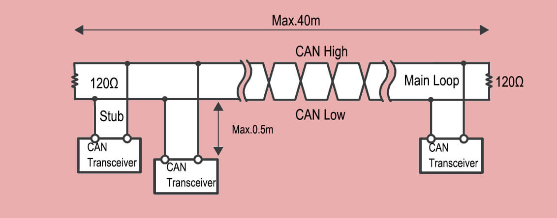
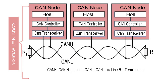
CAN Bus is a serial communication protocol that allows multiple devices or nodes to communicate with each other over a shared two-wire bus. It uses a differential signaling method, where the voltage difference between the two bus lines represents the logical states of 0 and 1. This differential signaling helps in noise immunity and allows for long-distance communication.
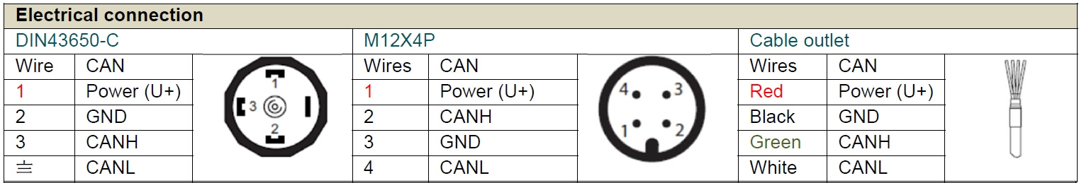
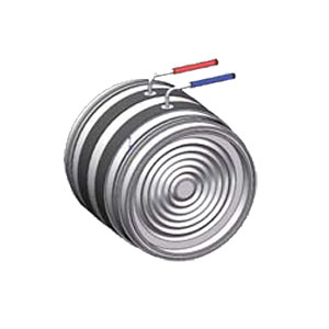
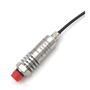
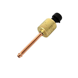
Fig: CAN pressure sensor wires connection
Key features of CAN Bus include
- Multi-master: CAN Bus allows multiple nodes to have equal access to the bus, meaning any node can initiate communication.
- Deterministic: CAN Bus has a deterministic nature, meaning that messages are transmitted in a predictable and timely manner. Each message has a unique identifier that determines its priority on the bus.
- Error detection and correction: CAN Bus has built-in error detection and correction mechanisms, such as checksums and acknowledgment, to ensure reliable data transmission.
- Scalability: CAN Bus supports a flexible network structure, allowing for easy addition or removal of nodes without affecting the overall system.
CAN (Controller Area Network)
- Speed/Max Bit Rate: Up to 1 Mbit/s at short distances, lower at long distances.
- Number of Pins: 2 (CAN_H and CAN_L for differential signaling).
- Data Transfer Distance: Up to 40 meters at 1 Mbit/s, can be extended to 1 kilometer at lower speeds.
- Noise Immunity: High, due to differential signaling and error checking.
- Inter-Connectivity: Multiple devices on the same bus using message-based communication.
- Typical Application: Vehicle network (automotive), industrial automation.
- Pros: Robust error handling, excellent noise immunity, great for networking multiple devices.
- Cons: More complex than I2C or SPI, lower speed.
What is CAN Bus pressure sensor
A CAN Bus Pressure Sensor is a type of pressure sensor that utilizes the Controller Area Network (CAN) protocol for data transmission. It measures pressure, typically of gases or liquids, and converts the measured pressure into digital data that can be interpreted by a microcontroller or computer over a CAN bus network.
The CAN protocol is a robust and reliable communication protocol widely used in automotive and industrial applications. It allows multiple devices to communicate with each other without a host computer.
A typical CAN Bus Pressure Sensor might have specifications like these:
1, Pressure Range:
The pressure range defines the minimum and maximum pressure that the sensor can measure. This could be anything from a few millibars (10mbar) up to thousands of bars, depending on the specific sensor.
Click here: Pressure Units Convertor
2, Accuracy:
This is a measure of how close the sensor’s output is to the true pressure. It’s typically specified as a percentage of the full-scale output.
For example, a sensor with a 0.25% accuracy rating can deviate by up to 0.25% from the actual pressure.
3. Output Data Rate:
The output data rate is the speed at which the sensor can send data over the CAN bus. This can range from a few kilobits per second to 1 megabit per second or more, depending on the sensor and the bus speed.
4. Supply Voltage:
This is the voltage that is required to power the sensor. Many industrial sensors operate at 24V DC, but other voltages like 12V DC are also common.
5. Operating Temperature:
This is the temperature range in which the sensor can operate reliably. For industrial sensors, this might typically be from -40°C to +85°C.
6. CAN Protocol:
The sensor will use either CAN 2.0A (Standard format with 11-bit identifiers) or CAN 2.0B (Extended format with 29-bit identifiers).
In a CAN network, messages (in this case, pressure readings) are sent as blocks of data called frames. Each frame has an identifier, which defines its priority on the network (lower values have higher priority), and up to 8 bytes of data.
When a pressure sensor sends a reading, it packages the pressure data into a CAN frame and transmits it on the bus. Other devices on the bus can then receive this frame and use the data for their own purposes.
This makes CAN Bus Pressure Sensors ideal for systems where you need to monitor pressure at multiple points, and where the data needs to be readily available to multiple devices. Their robustness and reliability also make them well-suited to harsh industrial environments and automotive applications.
Limitation and risk of CAN Bus pressure sensor
CAN (Controller Area Network) Bus pressure sensors are incredibly useful tools in a variety of applications, including automotive, industrial, and aerospace systems. They are designed to take the physical parameter of pressure and convert it into an electrical signal that can be interpreted by a control system. However, like any technology, they have limitations and risks that need to be understood to ensure efficient operation.
Limitations of CAN Bus Pressure Sensors
1, Bandwidth Limitations:
CAN Bus operates at different speeds, typically ranging from 40 kbps to 1 Mbps. If the network is crowded with too many devices or the data requirements exceed the bandwidth capabilities, it can lead to slower response times and potential data loss.
2. Distance Limitations:
The maximum cable length of a CAN Bus network depends on the data rate. Higher data rates allow for shorter cable lengths.
For example, at 1 Mbps, the maximum cable length is approximately 40 meters. This might limit its use in larger systems.
3. Node Limitations:
The CAN Bus protocol supports up to 110 nodes (devices) per network. If a system requires more than this, the network would need to be segmented or a different communication protocol might need to be used.
| Protocol | Distance | Speed/Max Bit Rate | Pins | Noise Immunity | Inter-Connectivity |
|---|---|---|---|---|---|
| NFC | Up to 0.1 m | Up to 424 kbit/s | N/A | Low | Point-to-point |
| I2C | Up to 2 m | Up to 3.4 Mbit/s | 2 | Moderate | Multi-master, multi-slave |
| TTL | Up to 2 m | Tens of Mbit/s | 1 per signal | Low | Depends on implementation |
| Parallel | Up to 3 m | Hundreds of Mbit/s | 20-50 | Moderate | Point-to-point |
| USB | Up to 5 m | Up to 20-40 Gbit/s | 4--24 | Very High | Point-to-point |
| HDMI | Up to 5 m | Up to 48 Gbit/s | 19 | Very High | Point-to-point |
| SPI | Up to a few meters | Up to 50 Mbit/s | 4 | Moderate | Single-master, multi-slave |
| UART | Up to 10 m | Up to 5 Mbit/s | 2 | Low | Point-to-point |
| RS232 | Up to 15 m | Up to 115.2 kbit/s | 9 | Low | Point-to-point |
| SDI-12 | Up to 100 m | 1200 bit/s | 3 | Moderate | Multi-drop |
| CAN | Up to 1000 m | Up to 1 Mbit/s | 2 | Very High | Multi-master |
| RS422 | Up to 1200 m | Up to 10 Mbit/s | 4 | High | Point-to-point, multi-drop |
| RS485 | Up to 1200 m | Up to 10 Mbit/s | 2 or 4 | Very High | Multi-drop |
| Fieldbus Foundation | Up to 1900 m | Up to 31.25 kbit/s | 2 | Very High | Multi-drop |
| 4-20mA HART | Up to 2000 m | 1200 bit/s | 2 | Very High | Multi-drop |
Risks of CAN Bus Pressure Sensors
1. Interference:
Like all electronic devices, CAN Bus pressure sensors are susceptible to electromagnetic interference (EMI) and radio frequency interference (RFI). This can distort the signal and lead to inaccurate pressure readings.
Check out details about How EMI and Noise work to Pressure Sensor
2, Failure Modes:
CAN Bus pressure sensors can fail in several ways. The sensor itself might become physically damaged, the electrical interface could fail, or a fault could occur in the CAN Bus network (like a short circuit).
3, Security:
Since CAN Bus is a network protocol, it is inherently vulnerable to cyber-attacks. Hackers can potentially intercept data, inject malicious code, or manipulate sensor readings. This is particularly concerning for systems where pressure sensor accuracy is paramount for safety.
4. Data Loss:
In a CAN Bus network, if a message is corrupted during transmission, it’s automatically discarded. If the network is highly congested or there are physical issues with the network (like poor cable quality or loose connections), this could potentially lead to significant data loss.
How to solve EMI/RFI interference
Electromagnetic interference (EMI) and radio frequency interference (RFI) can significantly affect the performance of CAN Bus pressure sensor systems.
Here are some strategies to minimize these interferences:
- Cable Shielding: you can use shielded cables for CAN Bus connections. The shield (typically made of a conductive material like copper or aluminum) absorbs the electromagnetic energy, reducing the amount that reaches the inner conductor. The shield should be grounded at one end to prevent circulating currents
- Proper Routing: Route cables away from sources of EMI/RFI such as motors, inverters, or power lines. If this isn’t possible, cross them at right angles to minimize interference.
- Twisted Pair Cables: CAN Bus networks often use twisted pair cables, where two conductors are twisted around each other. This configuration equalizes the effect of EMI on the wires, significantly reducing the noise that gets induced on the signal.
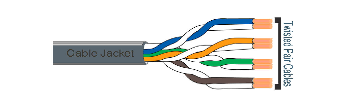
Click to check details: Pressure Sensor Cable 1; Pressure Sensor Cable 2;
- Ferrite Beads/Chokes: In some cases, the ferrite beads or chokes can be used on the cables. These components suppress high frequency noise by converting it into heat.
- Proper Grounding: An effective grounding system can help mitigate EMI/RFI. This involves grounding the device at one point (single-point grounding) or multiple points (multi-point grounding), depending on the frequency range being used.
CAN Network for Data Transmission
In the Controller Area Network (CAN), devices communicate by broadcasting messages over a shared network, rather than sending data to specific addresses. Each message carries a unique identifier which also dictates its priority on the network, with lower identifiers given higher priority.
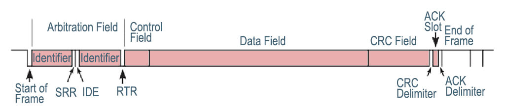
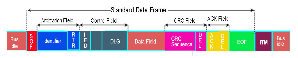
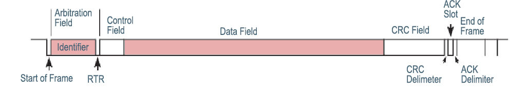
A single transmission unit, called a frame, is made up of several components. These include the Start of Frame, the Arbitration Field which houses the message identifier, the Control Field indicating the data length, the Data Field carrying the actual data of up to 8 bytes, a CRC Field for error checking, an Acknowledge Field, and the End of Frame.
When a device is ready to transmit data, it will first check if the network is free. If multiple devices attempt to transmit at the same time, the device with the highest priority message (lowest identifier) is allowed to continue while the others back off and retry later.
In terms of error management, CAN employs several mechanisms to ensure data integrity. The CRC Field allows devices to detect errors in a frame, and any device that detects an error can notify all other devices by sending an error frame. The network will then attempt to retransmit the incorrect frame.
Once a frame is successfully received by a device, that device sends an acknowledgment by overriding a specific bit within the Acknowledge Field of the frame.
All devices in a CAN network are connected to a single communication line, or “bus”, which is a topology that makes adding or removing devices from the network relatively easy.
Despite the complexity of the underlying mechanisms, CAN’s robustness and built-in error detection, coupled with its flexible topology, make it a popular choice for data transmission in situations where reliable communication is paramount.
Why CAN Bus is best for automobile industry
The CAN Bus pressure sensor has a number of benefits that make it particularly suitable for the automotive industry. Here are some of the key reasons:
1. High Data Integrity:
CAN Bus, or Controller Area Network, is a robust and reliable communication protocol. It features error detection and correction mechanisms, which maintain high data integrity. This is critical in automotive applications where the accuracy and reliability of sensor readings, such as pressure, can be a matter of safety.
2. Network Flexibility:
The CAN Bus allows multiple sensors to be connected in a network, leading to simplified wiring and lower costs. Unlike traditional point-to-point wiring systems, where a failure can isolate a sensor, the CAN Bus network maintains communication even in case of a single point failure, enhancing the robustness of the system.
3. Real-Time Data:
CAN Bus systems have a high data rate (up to 1 Mbit/s), enabling real-time or near-real-time data transmission. This speed is crucial in automotive applications, where quick responses to sensor readings (like pressure changes) are necessary.
4. Interference Resistance:
CAN Bus communication is differential, which means it uses two complementary signal lines. This method makes it resistant to electromagnetic interference, a common issue in the electrically noisy environment of an automobile.
5. Scalability:
As vehicles incorporate more features and capabilities, more sensors are needed. The CAN Bus system can easily incorporate additional sensors without significant changes to the existing network architecture.
6. Pressure Sensor Specifications:
CAN Bus pressure sensors are available with a wide range of pressure ranges, accuracy levels, and resolutions, making them suitable for different automotive applications. Some sensors also offer additional features like temperature compensation, which corrects the sensor output for changes in ambient temperature, further improving the reliability of the readings.
Click to download data sheet of EST3607CAN Fieldbus PressureTransmitter
For Automotive application
Absolutely. CAN Bus pressure sensors are integral to a variety of systems within modern automobiles. Here are several examples:
1. Engine Management:
CAN Bus pressure sensors are used to monitor various pressures within the engine, such as manifold absolute pressure (MAP), fuel pressure, oil pressure, and turbocharger boost pressure. These readings help the Engine Control Unit (ECU) optimize the combustion process, improve fuel efficiency, and reduce emissions.
2. Transmission Control:
In automatic transmissions, pressure sensors monitor the hydraulic pressure. The Transmission Control Unit (TCU) uses this information to control gear shifts, ensuring smooth operation and prolonging the transmission’s lifespan.
3. Tire Pressure Monitoring System (TPMS):
CAN Bus pressure sensors can be used in each wheel to monitor tire pressure. When pressure drops below a certain level, the system alerts the driver, thereby helping to prevent accidents caused by underinflated tires and improving fuel efficiency.
4. Brake System:
In braking systems, especially in Anti-lock Braking System (ABS) and Electronic Stability Control (ESC), pressure sensors monitor the hydraulic pressure. They help in modulating the braking force applied to each wheel, improving vehicle safety during high-speed stops or on slippery surfaces.
5. HVAC System:
In the Heating, Ventilation, and Air Conditioning (HVAC) system, pressure sensors monitor the refrigerant pressure. This measurement helps maintain the efficiency of the air conditioning system and can alert the driver or maintenance personnel to potential leaks or failures.
6. Power Steering:
In vehicles with hydraulic power steering, pressure sensors are used to monitor the hydraulic fluid pressure. This information helps control the power-assist level to the steering mechanism, improving driver comfort and vehicle responsiveness.

Wrap up
A CAN Bus Pressure Sensor uses the Controller Area Network (CAN) protocol to transmit pressure data reliably.
The sensor broadcasts its data as messages over the network, with each message having a unique identifier that also determines its priority.
A single message, or frame, includes the message identifier, data length, actual data (up to 8 bytes), and fields for error checking and acknowledgment.
During transmission, if multiple sensors attempt to send data simultaneously, the one with the highest priority message continues while the others retry later.
CAN includes robust error detection mechanisms; if an error is detected, all devices are notified, and the erroneous frame is retransmitted. Upon successful receipt of a frame, devices send an acknowledgment.
All sensors are connected to a single communication line, simplifying network modifications. Despite its complexity, the CAN protocol’s robustness, error detection capabilities, and flexible topology make CAN Bus Pressure Sensors a reliable choice for accurate, real-time pressure monitoring in demanding environments.