Range Setting
The process of setting the scale for the 4 mA and 20 mA points is called Range setting (re-ranging). “Calibrated range” or “calibration range” are two other names given to the scale.
This defines how the transmitter output is at 4 mA and what input is required to achieve this reading. 4 mA is also known as the Lower Range Value (LRV) or as “zero” meaning 0%.
The reading at which the input is 20 mA is the Upper Range Value (URV), also known as “full scale”, meaning 100%. People often confuse the word span and take it along the same lines as URV, but that completely changes the meaning of the concept.
The magnitude of difference between the URV and LRV is referred to as as span. Take this example to elaborate on the concept. When the LRV is 20 and the URV is 100, the span will be 80.
When using Fieldbus, PROFIBUS, and WirelessHART, range setting is not required for such devices in most applications so there’s no need to use 4-20 mA.
It’s important to note and remember that a firmware in the transmitter microprocessor is used to calculate what the output current value should be. The mathematical function ensures accurate reading.
Internally, the 4-20 mA/HART transmitter will be:
Percentage = (PRIMARY_VARIABLE – LRV) / (URV – LRV) * 100 [%]
Analog Current = (PRIMARY_VARIABLE – LRV) / (URV – LRV) * 16 + 4 [mA]
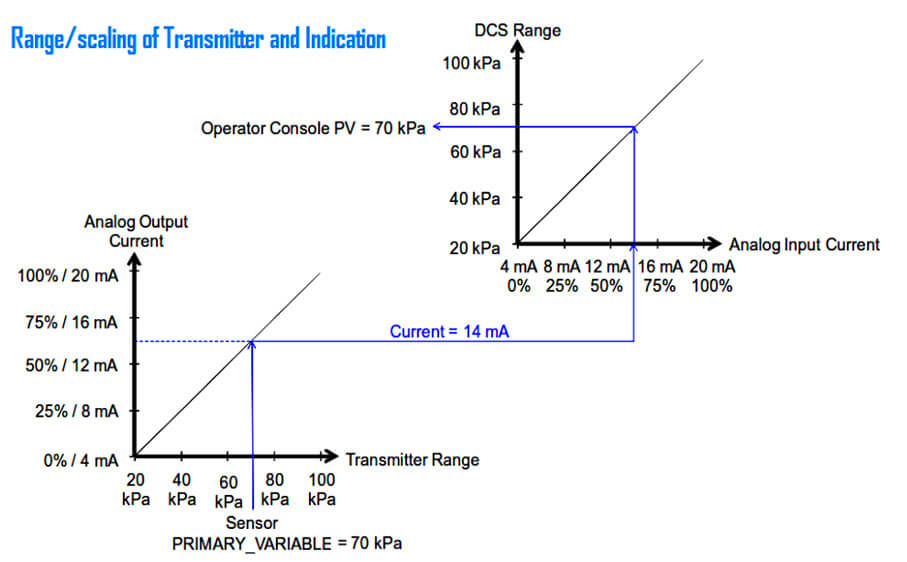
Internally the 4-20 mA control system, recorder, or indicator computes:
Percentage = (Current – 4) / 16 * 100 [%]
PV = (Current – 4) / 16 * (URV – LRV) + LRV [E.U.]
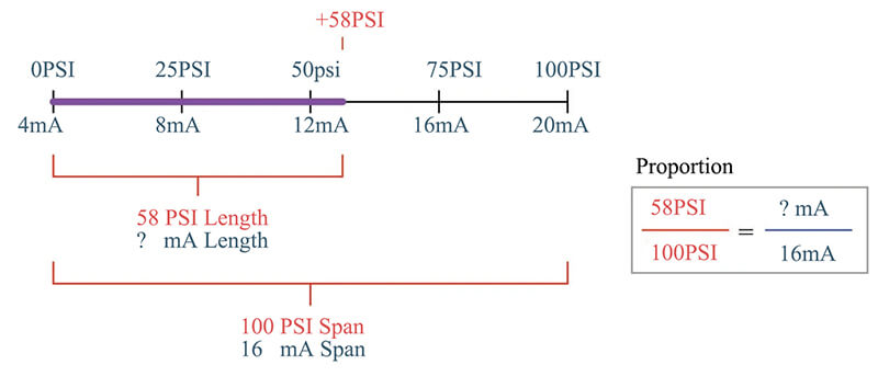
LRV to URV range limits the analog output of a transmitter. Hence, the analog output does not benefit from the full LSL to USL capability of the sensor.
![]()
Fig: The measurements derived in an analog signal system are restricted within range values.
On the other hand, the LRV to URV range does not confine FOUNDATION Fieldbus, PROFIBUS, and WirelessHART transmitters as well as the digital output of 4-20 mA/HART transmitters. However, the full LSL to USL capability of the sensor does benefit them.
![]()
Fig: The measurements derived in a digital bus signal system utilize full sensor limits.
Transmitter range setting can be done from a central location, remotely since it doesn’t require any input. Range must be set within the Lower Sensor Limit (LSL) and Upper Sensor Limit (USL).
For example, when the n input is 0 bar, just set the range of pressure transmitter to get 4 mA and 20 mA when the pressure is 40 bar. Span is also included here, though, the input is 0 bar, just set the range of pressure transmitter to get 4 mA and 20 mA when the pressure is 40 bar. Span is also included here, though, transmitters usually have a minimum span.
In order to get high analog output resolution and percentage accuracy the difference between URV and LRV must exceed the minimum span. In case it doesn’t, the results will be too poor. This difference occurs because the quantization error gets amplified too much with a small span.
The physical restrictions of the sensor mostly control the sensor limits. The sensor limits are always read-only since they cannot be changed. There’s a diverse range of sensors, each with a different set of limits. Take the various RTDs and thermocouples, for example. In order to accommodate the range of the application in temperature applications, a sensor type is selected that has sufficient sensor limits.
To get wider sensor limits and to accommodate a wider range, it’s essential to purchase a new sensor. This becomes necessary because the range limits are physical and cannot be changed.
Likewise, pressure transmitters can be set at different sensor module limits that range from low to high pressure. In order to get wider sensor limits and to accommodate a wider range, it is necessary to purchase a new sensor.
Definition of Terms
Regular Terms Definition
Zero elevation: For an elevated-zero range, the amount of the measured variable zero is above the lower range-value.
Zero suppression: For a suppressed-zero range, the amount of the measured variable zero is below the lower range-value.
Range setting can only be used for transmitters with 4-20 mA analog output. It is not applicable for pure digital solutions like FOUNDATION fieldbus (FF) or WirelessHART transmitters.
Since FF and WirelessHART transmitters have no 4-20 mA analog output, the need to set 4 mA and 20 mA range points doesn’t even exist. When using 4-20 mA systems, it’s necessary to set the range in both the transmitter and controller.
When using FF and PROFIBUS, the range is set in the controller. This negates the need to set the range in the transmitter. This change is often confusing for some beginners.
But it’s important to remember that there is an exception here, which means that FF, WirelessHART, and PROFIBUS transmitters may be for differential pressure (DP) flow and level measurement, where the end-points of the DP scale (e.g. 0250 inH2O in XD_SCALE) and corresponding flow or level scale (e.g. 0-400 bbl/day in OUT_SCALE).
The step enables DP transmitters to indicate in flow or level units locally. Although FF and PROFIBUS devices provide the option of setting a range in the transmitter, it isn’t always used for the application.
![]()
Fig: An analog signal system requires range, current trims, and scaling, whereas a digital bus system does not need any of these.
Nevertheless, when purchasing FOUNDATION fieldbus (FF) and WirelessHART transmitters for sizing purposes, the nominal operating range must be specified. This enables the device supplier to pick the appropriate sensor model.
The desired engineering unit in the device must also be selected. There may be a need for the DCS to get a range set in the database as scaling end-points for bar graphs and trend.
Even though there is no range in the FOUNDATION fieldbus or WirelessHART device, the DCS will also need a range for PID control. For control applications, the level is usually expressed in percentage of full tank.
Engineering unit is the output of both the FF transducer block and the AI function block. In order to get the PV for most applications, it’s not always necessary to set range in either block.
On the other hand, there are many systems that use the range in the FF transmitter AI block. They use it to scale the faceplates bargraphs. If the need arises to increase the resolution of the faceplate bargraph, a narrower range is set to achieve the desired result.
For instance, if a range is set in the AI block, the percentage of range can be seen from the FIELD_VAL parameter.
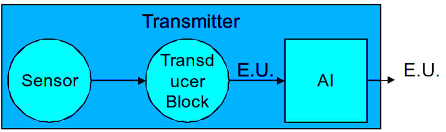
Fig: Digital transmitters internally operate in engineering units
There are typically two ways to set the range of the transmitter:
- Direct numeric value entry
- To applied input
Direct numeric value entry
When the desired lower and upper range values are simply entered in from device software or handheld field communicator, the process is simply known as direct numeric value entry. The range values are then sent to the transmitter to start the process. To understand this better, take the example of entering the 20 to 100 kPa.
To applied input
Range setting to applied input requires a physical input corresponding to the desired range value to be applied to the transmitter. Most of the times, this is used in level measurement applications. Since the mounting (datum) of the level transmitter plays an integral role here, it’s recommended that the range be adjusted at site. Setting it in a lab won’t get accurate results. In short, it is a zero cancelation such as DP wet leg.
In order to complete the process, the tank is emptied to its lower level first. The next step is to send the “set PV LRV command” to the transmitter. This step helps set the lower range value to whatever the recommended input is.
In the case of a DP level transmitter, if the pressure is 20 kPa when the tank is empty (the pressure tap is slightly below the datum), this becomes the new lower range value. This way, it’s possible to get a 0% reading, and the analog output current is 4 mA.
To get the opposite reading, the tank is filled to its upper level and then the “set PV URV” command is sent to the transmitter. This sets the upper range value to accommodate the required input. When the pressure is 100 kPa with a full tank, this becomes the new upper range value, thus ensuring the reading is 100% and analog output current is 20 mA.
In between, the reading is linear. It’s important to note here that the technician need not know what the physical input is. He just needs to know that the tanks are full and empty.
In order to cancel wet-leg for DP transmitters in all kinds of application including flow, the set PV LRV command is quite common. These commands are the same as pushing the ‘zero’ and ‘span’ buttons that are found on some transmitters.
ANSI/ISA–51.1 Definition of Terms
- Range:The area between the confines within which a quantity is measured, received, or transmitted. This is expressed by stating the lower and upper range-values.
For example:
- 0 to 200°F
- –20 to +150°F
- 20 to 150°C
- Range-value, lower (LRV):The lowest value of the measured variable that a device is attuned to measure.
- Range-value, upper (URV):The highest value of the measured variable that a device is attuned to measure.
- Range-limit, lower (LSL):The lowest value of the measured variable that a device can be attuned to measure.
- Range-limit, upper (USL):The highest value of the measured variable that a device can be attuned to measure.
- Span:The algebraic difference between the upper and lower range-values.
For example:
- Range 0 to 200°F, Span 200°F
- Range –20 to 150°F, Span 170°F
- Range 20 to 100°C, Span 120°C
Note: FOUNDATION fieldbus uses the term “scale” in place of “range”
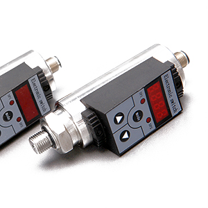
Find out: HART Protocol EST4300 Smart Pressure Transmitter in our Shop
You may also interest in:
- Basics of DP Transmitter
- How 4-20mA Transmitter Works
- Capacitance Differential Pressure Transmitter Working Principle
- DP Transmitters Applications
- Fieldbus, ProfiBus and HART Protocols
- Some Important Transmitter Calibration Terms You Need to Know
- Sensor Trim – Smart Transmitter Calibration Tutorial Part 1