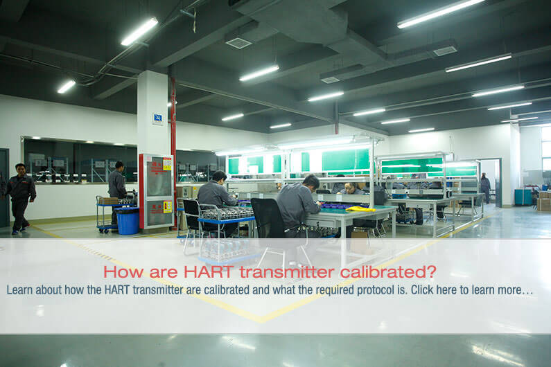
How are HART transmitter calibrated?
As the field instrumentation in process plants is coming under a more sophisticated metrological discipline, some much-needed changes will be incorporated in the latest models. Most new field instruments are now smart digital instruments. The best thing that sets apart HART (Highway Automated Remote Transducer) protocol from the rest is that it shares characteristics of both analog and digital control systems.
Precision analog source/measure capability and digital communication are required to service these instruments properly. Previously, this operation required two separate tools; a calibrator and a communicator. In the recent models, these capabilities are available in a single HART Process Calibrator. This technological advancement allows technicians to service a HART instrument quickly and effectively.
What is the HART protocol?
HART stands for Highway Addressable Remote Transducer.
The HART protocol uses 1,200 baud Frequency Shift Keying (FSK) based on the Bell 202 standard to superimpose digital information on the conventional 4-20 mA analog signal. An independent organization maintains the HART Communication Foundation. The HART protocol is an industry standard that has been developed to define the communications protocol between a control system and intelligent field devices.
With over five million HART field instruments installed in over 100,000 plants worldwide, HART is the most widely used digital communication protocol in the process industries.
HART Protocol:
- Is compatible with traditional analog devices.
- Uses multidrop networks and supports cabling savings.
- Is backed up by all of the major vendors of process field instruments.
- Utilizes smart instrument networks and reduces operation costs through improved management.
- Preserves present control strategies and allows conventional 4-20 mA signals to co-exist with digital communication on existing two-wire loops.
- Provides vital insight for installation and maintenance. For instance, Tag-IDs, measured values, range and span data, product information and diagnostics.
How HART instruments calibrated?
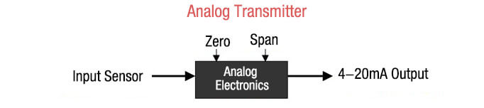
Calibration of an analog transmitter doesn’t cause any hassles and is fairly straightforward. With the help of an As-Found test and by using the zero and span adjustments, it’s easy to set the correct relationship between the input signal and the 4 – 20 mA output. On the other hand, As-Left test completes the calibration process.
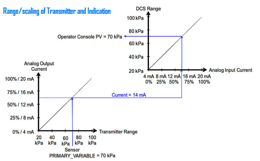
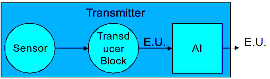
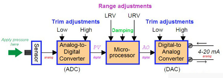
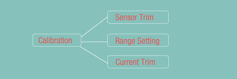
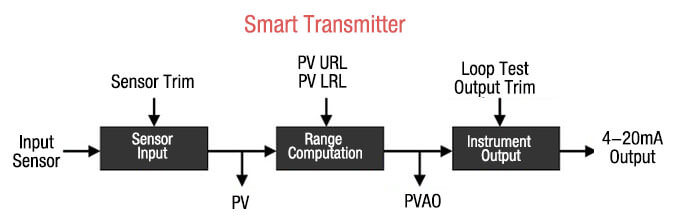
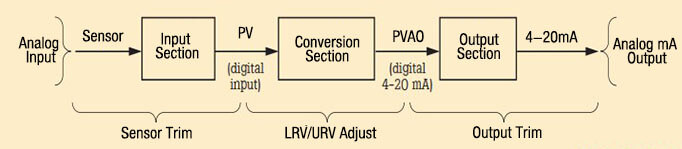
Since a HART instrument has three distinct stages, it is classified as a more complex process. The relationship between an input sensor and the PV, or primary variable, is set with the help of the sensor input stage. The PV is denominated in engineering units, for instance, psi or oF. It’s easy to adjust the Sensor Input stage by digitally trimming Sensor Trim.
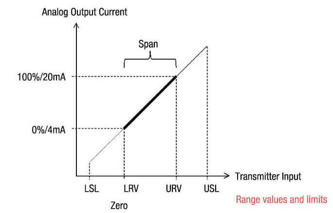
The second stage is a computational stage, which establishes the relationship between PV (Primary Variable) and PVAO (Primary Variable Analog Output). The range is scaled by assigning the PV Upper Range Limit and Lower Range Limit values, where PVAO is a digital value of the 4-20 mA output signal.
The final stage, also known as the Instrument Output, is set digitally with Output Trim. Using a HART configurator or communicator, these trims and the process of entering the URV and LRV is performed. A separate calibrator provides the precision analog source and measures functions for accurate readings.
The calibration approach for a HART instrument is determined by how the transmitter outputs are used. It may be treated as an analog transmitter, if only the 4-20 mA analog signal is used. The correct relationship between input sensor and 4-20 mA analog output are set using the transmitter’s manual zero and span buttons. Using the digital setting is another way to get the PV LRV and PV URV,
In this scenario, however, it’s plain to see that the Sensor Input stage has not been adjusted properly. If a communicator is used to read the digital value PV, it is likely to be incorrect. The result will be the same even if the 4-20 mA output is correct.
A more rigorous approach is required if the control system will use any of the digital signals. Sensor Trim must be used to set the input stage correctly if the system uses PV. The next step is to digitally assign PV LRV and PV URV and to avoid using the manual zero and span buttons to change the readings.
For the final step, the Output Trim correctly sets the relationship between the PVAO and the 4-20 mA analog output.
Is HART calibration required?
Ever heard that the accuracy and stability of HART instruments eliminate the need for calibration or that calibration can be accomplished by re-ranging field instruments with a HART communicator? That’s a common misconception that needs to be set right. Another misconception is that smart instruments can be remotely calibrated by the control system. None of these statements are true!
The truth is that all instruments drift. Calibration doesn’t mean re-ranging with just a communicator. A precision calibrator or standard is required to do an efficient job. Regular performance verification with a calibrator that is traceable to national standards is necessary due to:
- Regulations governing consumer safety, environmental protection, and occupational safety.
- Quality programs such as ISO 9000 standards for all instruments that have a profound impact on product quality.
- Shifts in performance of electronic instruments over time, which can be due to exposure of the electronics. These discrepancies also occur if the primary sensing element is exposed to field environmental factors such as temperature, humidity, pollutants, and vibration.
- Commercial requirements such as weights, measures, and custody transfer. Since performance checks might discover problems that are not directly related to instrumentation, such as solidified or congealed pressure lines, installation of an incorrect thermocouple type, or other errors and faults, regular calibration is a sensible option.
A calibration procedure consists of three major steps. The first one is the verification (As Found) test. Next comes the adjustment to within acceptable limits, if necessary, and the last step entails a final verification (As Left) test, if any adjustments have been made. Data from the calibration is collected and then used to compile the calibration report that documents instrument performance over time.
All instruments, even HART instruments, have to be calibrated on a regular basis. This preventive maintenance schedule enables a smooth process. In order to ensure that an instrument never drifts out of tolerance, the calibration interval should be short enough. It’s also essential to ensure that the interval is long enough to avoid unnecessary calibrations. Alternatively, critical process requirements, such as calibration, before each batch can also determine the interval.
Find out: HART Protocol EST4300 Smart Pressure Transmitter in our Shop
You may also interest in:
- Capacitance Differential Pressure Transmitter Working Principle
- DP Transmitters Applications
- Fieldbus, ProfiBus and HART Protocols
- Some Important Transmitter Calibration Terms You Need to Know
- Sensor Trim – Smart Transmitter Calibration Tutorial Part 1
- Range Setting – Smart Transmitter Calibration Tutorial Part 2
- Current Trim – Smart Transmitter Calibration Tutorial Part 3