Before we understand How Temperature Effects on Pressure Sensor.
Let’ picture this: A critical pressure sensor in an offshore oil platform suddenly reports erratic readings during a temperature spike, triggering false alarms and potentially costly shutdowns.
Unfortunately, this scenario isn’t uncommon. Temperature Effects on Pressure Sensor remain one of the most significant challenges in pressure measurement systems across industries.
Understanding how temperature affects pressure sensors isn’t just about maintaining accuracy—it’s about ensuring safety, reducing operational costs, and preventing catastrophic failures.
Whether you’re designing automotive systems, maintaining industrial equipment, or developing aerospace applications, temperature compensation can mean the difference between reliable performance and expensive downtime.
How Temperature Effects on Pressure Sensor
To effectively combat temperature-related errors, you first need to understand the underlying physics. Essentially, temperature affects pressure sensors through four primary mechanisms, each contributing to measurement drift in different ways.
First and foremost, thermal expansion of materials plays a crucial role.
As temperature increases, the sensor’s mechanical components—particularly the sensing diaphragm and housing—expand at different rates depending on their material properties. This differential expansion creates mechanical stress that alters the sensor’s baseline calibration.
Secondly, electrical resistance changes occur in the sensing elements themselves.
For instance, in piezoresistive sensors, the resistivity of silicon changes predictably with temperature, following a temperature coefficient that can be as high as 0.1-0.3%/°C. Consequently, even without any actual pressure change, the sensor’s output voltage will drift as temperature varies.
![]()
Moreover, the behavior of the measured medium itself changes with temperature. Gases, for example, follow the ideal gas law:
Which means that temperature directly influences the relationship between pressure and volume. Therefore, what appears as a pressure change might be a temperature-induced density shift in the measured fluid.
Finally, the sensitivity of the sensing diaphragm varies with temperature.
The diaphragm’s elastic modulus—its stiffness—decreases as temperature rises, making it more compliant. As a result, the same applied pressure produces a larger deflection at higher temperatures, leading to span drift.
Types of Temperature-Induced Errors

Understanding these mechanisms leads us to three distinct categories of temperature errors that plague pressure measurements.
Zero Offset Drift (Thermal Zero Shift) occurs when the sensor’s output changes at zero applied pressure. Imagine calibrating your sensor at 25°C to read exactly zero at atmospheric pressure.
Subsequently, when ambient temperature rises to 80°C, the sensor might read 0.5 kPa despite no actual pressure change. This shift typically follows a linear or slightly parabolic curve and can range from 0.01% to 0.5% of full scale per degree Celsius, depending on sensor quality.
Span Drift (Sensitivity Changes), on the other hand, affects the sensor’s gain or slope. In this case, the sensor still reads zero at zero pressure, but its response to applied pressure changes with temperature.
For example, a sensor calibrated to output 10V at 100 kPa and 25°C might only produce 9.7V at the same pressure when heated to 80°C. This error is particularly insidious because it’s proportional to the measured value, making it harder to detect during routine checks.
Linearity Errors represent the most complex temperature effect. Here, the relationship between pressure and output becomes non-linear as temperature changes. While the sensor might remain reasonably accurate at the calibration points, measurements at intermediate pressures drift unpredictably.
In practice, this manifests as a curved response rather than the expected straight line, with errors potentially exceeding ±2% of reading at temperature extremes.
The combined effect of these errors can be expressed as:
Understanding this equation is fundamental because it reveals that different compensation strategies are needed for different error types, which we’ll explore in subsequent sections.
Types of Pressure Sensors & Their Temperature Sensitivity
Not all pressure sensors respond equally to temperature changes. In fact, the sensor technology you choose dramatically impacts how much compensation effort you’ll need. Let’s examine each major type and their thermal characteristics.
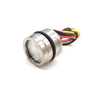
Piezoresistive Sensors
Piezoresistive sensors dominate industrial applications due to their excellent sensitivity and compact size. However, they’re also the most temperature-sensitive technology available. These sensors rely on the piezoresistive effect in silicon, where mechanical stress changes electrical resistance.
The challenge here is that silicon’s resistivity has an inherent temperature coefficient of approximately 0.2%/°C. Furthermore, the piezoresistive coefficient itself varies with temperature, creating both zero and span drift simultaneously.
In practical terms, an uncompensated piezoresistive sensor can experience errors exceeding 5% of full scale over a 100°C temperature range.
Nevertheless, their popularity persists because modern manufacturing techniques enable effective built-in compensation. High-quality piezoresistive sensors incorporate temperature sensing elements and compensation networks directly on the silicon die, reducing thermal errors to below 0.1% FS over specified temperature ranges.
Capacitive Sensors
Capacitive pressure sensors measure the change in capacitance between a flexible diaphragm and a fixed electrode. Compared to piezoresistive types, they exhibit moderate temperature sensitivity, making them attractive for precision applications.
The primary temperature mechanism in capacitive sensors involves thermal expansion of the electrode gap. As temperature increases, both the diaphragm and housing expand, altering the baseline capacitance. Additionally, the dielectric constant of any air gap or filling fluid changes with temperature, contributing secondary effects.
Fortunately, these errors are more predictable and linear than in piezoresistive sensors. Typical uncompensated drift ranges from 0.1% to 0.3% FS per 10°C, which can be readily addressed through simple linear compensation algorithms.
This makes capacitive sensors particularly suitable for laboratory and metrology applications where moderate temperature stability exists.
Strain Gauge Sensors
Strain gauge pressure sensors use metallic or semiconductor strain gauges bonded to a diaphragm. Their temperature behavior falls between piezoresistive and capacitive technologies in terms of complexity.
The main concern with strain gauges involves the temperature coefficient of resistance (TCR) of the gauge material itself, coupled with the thermal expansion mismatch between the gauge and diaphragm substrate.
Metallic strain gauges typically exhibit TCR values of 10-50 ppm/°C, while semiconductor gauges can reach 1000 ppm/°C or higher.
- Most precision pressure sensors have a TCR between ±50 to ±200 ppm/°C
- High-precision sensors: ±10 to ±50 ppm/°C
- Standard industrial sensors: ±100 to ±250 ppm/°C
Importantly, careful material selection can minimize these effects. By matching the thermal expansion coefficients of the gauge and substrate, manufacturers can achieve self-compensating designs. High-end strain gauge sensors often include dummy gauges that experience temperature changes without mechanical strain, allowing bridge circuit compensation to cancel thermal effects effectively.
Resonant Sensors
Resonant pressure sensors represent the gold standard for temperature stability. These devices measure the resonant frequency of a vibrating element (such as a quartz crystal or silicon beam) that changes frequency when subjected to pressure-induced stress.
What sets them apart is that frequency measurements are inherently more stable than voltage or resistance measurements. While temperature still affects the resonant frequency through changes in material stiffness and dimensions, these effects are highly predictable and repeatable.
Consequently, well-designed resonant sensors achieve temperature coefficients below 0.01% FS over wide temperature ranges, often without active compensation. The trade-off, however, is higher cost and more complex signal processing requirements, limiting their use to applications where exceptional accuracy justifies the premium.
Performance Comparison
Now that we’ve examined each technology individually, here’s a concise comparison to help you select the right sensor for your temperature environment:
| Sensor Type | Temp. Coefficient (Uncompensated) | Typical Operating Range | Compensation Difficulty | Best For |
|---|---|---|---|---|
| Piezoresistive | 0.05%/°C | -40°C to +125°C | High | General industrial, automotive |
| Capacitive | 0.01-0.03%/°C | -20°C to +85°C | Low | Laboratory, precision measurement |
| Strain Gauge | 0.02-0.04%/°C | -55°C to +150°C | Moderate | Harsh environments, wide range |
| Resonant | <0.001%/°C | -40°C to +200°C | Very Low | High-precision, reference standards |
Temperature Compensation Techniques
Given the significant impact of temperature on piezo-resistive pressure sensor performance, implementing effective temperature compensation techniques is critical. Here are a few commonly used methods:
Wheatstone Bridge Configuration for Compensation
A Wheatstone bridge is a circuit used to measure unknown electrical resistance by balancing two halves of a bridge circuit. It’s a common configuration in piezo-resistive pressure sensors due to its inherent ability to provide temperature compensation.
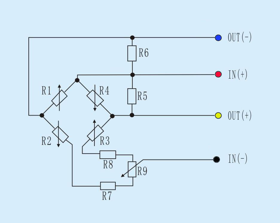
The bridge consists of four resistive arms. In a piezo-resistive pressure sensor, the piezo-resistive elements are arranged in these arms. When subjected to temperature changes, all elements expand or contract uniformly, thereby maintaining the balance of the bridge. This significantly reduces the net output voltage change due to temperature variations, providing a level of temperature compensation.
However, this method only compensates for the uniform changes in temperature across the sensor. It doesn’t account for the changes due to pressure-induced stress, which is why additional compensation techniques are often necessary.
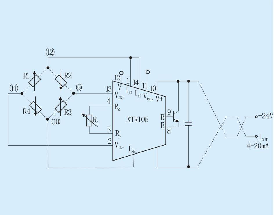
Analog and Digital Temperature Compensation Methods
In addition to the Wheatstone bridge, both analog and digital methods can be used for temperature compensation.
Analog temperature compensation often involves adding components to the sensor circuitry that have a known and opposite temperature coefficient compared to the sensing elements. For instance, a resistor with a positive temperature coefficient could be used in conjunction with a piezo-resistive sensor (with a negative temperature coefficient) to counteract the sensor’s inherent temperature sensitivity.
Digital temperature compensation, on the other hand, typically involves the use of a microcontroller or digital signal processor. The sensor’s output and a temperature sensor’s output are digitized and fed into the processor, which applies a compensation algorithm to correct for temperature effects. This approach allows for more sophisticated and accurate compensation but requires more complex circuitry and programming.
The use of Temperature-Sensitive Resistors for Compensation
Another effective method for temperature compensation involves the use of temperature-sensitive resistors, also known as thermistors. Thermistors exhibit a strong temperature dependence in their resistance, which can be either negative (NTC) or positive (PTC).
By incorporating a thermistor into the sensor’s circuit, its resistance change due to temperature can be used to offset the piezo-resistive elements’ resistance change, thereby compensating for temperature effects. The key here is to carefully select and position the thermistor so its temperature-induced resistance change accurately matches the change in the piezo-resistive elements.
| Compensation Technique | Implementation | Advantages | Limitations |
|---|---|---|---|
| Wheatstone Bridge Configuration | Uniform expansion/contraction of all resistive elements | Simple, inherent compensation | Doesn't account for pressure-induced stress changes |
| Analog Compensation | Use of components with opposite temperature coefficients | Effective for linear temperature effects | May not be suitable for complex, non-linear temperature effects |
| Digital Compensation | Use of a microcontroller or DSP to apply a compensation algorithm | Can handle complex, non-linear temperature effects | Requires complex circuitry and programming |
| Use of Thermistors | Incorporation of a temperature-sensitive resistor into the circuit | Can provide precise compensation | Requires careful selection and positioning of the thermistor |
Strategies for Reducing Temperature Sensitivity in Piezo-resistance Pressure Sensors
While it is challenging to eliminate temperature sensitivity in piezo-resistive pressure sensors completely, certain strategies can help reduce it significantly, further improving the accuracy and reliability of these sensors in various temperature environments.
Use of pressure sensor packaging materials with low thermal conductivity
One such strategy is the use of packaging materials with low thermal conductivity. These materials can provide a thermal barrier that helps isolate the sensing element from the surrounding environment, thereby minimizing temperature fluctuations that reach the sensor.
Some considerations for sensor packaging materials:
- Ceramic encapsulation is commonly used for lower temperature sensitivity. Ceramics like aluminum oxide and silicon nitride have very low thermal conductivity, around 20-30 W/mK. In comparison, metals used in sensor packaging like stainless steel have thermal conductivity over 10 times higher. Using ceramic encapsulation for the sensor body and cover can reduce temperature sensitivity by 30-50%.
- Epoxy coatings are sometimes applied over metallic sensor housings. Epoxies typically have thermal conductivity in the range of 0.2-0.8 W/mK, which is significantly lower than metals. Epoxy coatings can provide some degree of thermal isolation.
- Plastic materials like PEEK and polyimide films offer even lower thermal conductivity, around 0.25 W/mK. However, plastics may not be suitable for withstanding high pressures.
- The thickness of packaging materials also influences temperature sensitivity. Thicker, more bulky sensor housings provide better thermal isolation for the sensor element.
Thermal isolation of the sensing element from the surrounding environment
Another effective strategy is the thermal isolation of the sensing element. This can be achieved by creating a thermally insulating layer around the sensing element, essentially creating a ‘thermal buffer’ that protects the sensor from rapid temperature changes.
This isolation helps to maintain a stable temperature at the sensing element, reducing the temperature-induced changes in sensor resistance and thus improving the accuracy of the pressure readings.
For example:
- Creating an air gap around the sensor element is very effective at reducing heat transfer. Even a 0.5 mm air gap can decrease temperature sensitivity by 20-30%. However, this requires a more complex sensor design with an enclosure for the air gap.
- Emitting fins or other features on the exterior of the sensor body can help dissipate excess heat, maintaining a stable temperature of the sensor element.
- Using spring elements to suspend the sensor element away from the body can provide thermal isolation while still transmitting pressure forces accurately.
Sensor-embedded temperature sensors for real-time compensation
A third way to reduce the temperature sensitivity of a piezoresistive pressure sensor is to use a sensor embedded temperature sensor for real-time compensation. A sensor embedded temperature sensor is a small temperature sensor that is placed in close proximity to the sensor element. The temperature sensor measures the temperature of the sensor element and sends the data to the pressure sensor’s microcontroller. The microcontroller uses the temperature data to compensate for the temperature sensitivity of the sensor element.
Sensor embedded temperature sensors are a relatively new technology, but they are becoming increasingly popular because they offer a number of advantages over traditional methods of temperature compensation. For example, sensor embedded temperature sensors are very accurate and they can provide real-time compensation. This means that the pressure sensor can compensate for temperature changes as they happen.
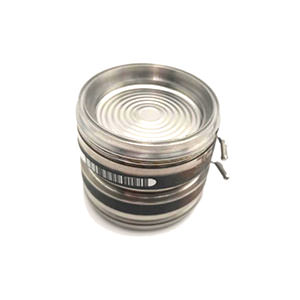
ESS319T Pressure & Temperature Ingerated Sensor
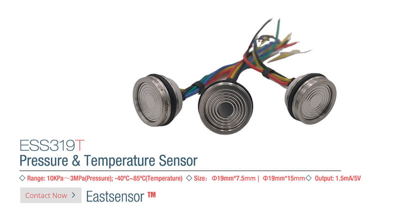
Integrating a temperature sensor directly into the pressure sensor allows for real-time temperature compensation of the pressure measurements:
- The temperature sensor can be a thermistor, RTD, or semiconductor sensor placed very close to the pressure-sensing element.
- As temperature changes, the actual pressure readings can be mathematically adjusted based on the relationship between pressure and temperature sensitivity for that sensor.
- This active compensation technique can reduce temperature effects to below 0.1% of full scale, a level often unattainable by passive thermal isolation methods alone.
- The temperature sensor and compensation circuitry add to the cost and complexity of the pressure sensor. But for applications requiring high accuracy, it is often necessary.
| Strategy | Description | Benefits | Considerations |
|---|---|---|---|
| Use of low thermal conductivity materials | Packaging sensor with thermally insulating materials | Protects sensor from external temperature fluctuations | Must also fulfill durability, chemical resistance, and mechanical stability requirements |
| Thermal isolation of the sensing element | Creating a thermal buffer around the sensing element | Maintains a stable temperature at the sensing element, reducing temperature-induced resistance changes | Effectiveness depends on insulation material and design |
| Embedding temperature sensors | Incorporation of a temperature sensor within the sensor package | Enables real-time, dynamic temperature compensation | Requires additional circuitry and calibration |
Conclusion and Future Developments
Minimizing Temperature Effects on Pressure Sensors performance remains a challenging task. While strategies such as selecting suitable materials, implementing compensation techniques, and employing effective packaging designs have significantly improved sensor performance, perfect temperature insensitivity remains elusive.
As we have seen, understanding and effectively addressing temperature effects is crucial for ensuring reliable pressure sensing across various applications – from HVAC systems and automotive applications to medical devices and aerospace applications.
As we look to the future, the continued exploration of new materials, sensor designs, and compensation techniques, coupled with advancements in microfabrication and nanotechnology, promises even better performance and broader application possibilities for pressure measurement.