What is Span Error
Span error is one of the main types of errors seen in pressure sensor measurements. It refers to the deviation of the sensor’s output span from the ideal specified value. And it is usually expressed as a percentage of the ideal span value. The lower the span error, the more accurate the sensor.
Let’s say we have an ideal pressure sensor that is specified to output 1 to 5 volts as the input pressure changes from 0 to 100 PSI. The sensor’s ideal output span should be 5-1 = 4 volts.
However, in reality, due to various factors like component tolerances, non-linearity, hysteresis etc. the sensor’s actual output span may differ from the ideal 4 volt span. This difference is known as the span error.
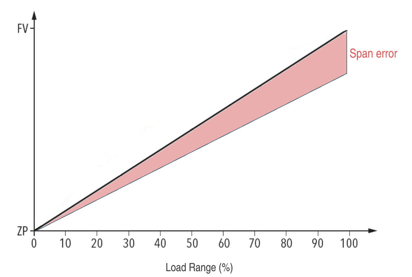
For example, if the sensor’s actual output changes from 0.8 volt at 0 PSI to 4.8 volt at 100 PSI, then the actual span is 4.8-0.8 = 4 volt. Since the ideal span is 4 volt, the span error in this case is 0%.
However, if the sensor’s actual output changes from 1 volt to 5.1 volt, then the actual span is 5.1-1 = 4.1 volt. In this case, the span error will be (4.1- 4)/4 = 2.5% positive span error.
How the span error affects the pressure sensor accuracy
Imagine a pressure sensor is specified to output 1-5 volts as the pressure changes from 0-100 PSI. This is the ideal span of 4 volts.
But the sensor’s actual span may be 4.1 volts due to factors like component tolerances, non-linearity, etc. This means a positive span error of 2.5% compared to the ideal span.
Now let’s see how this affects the sensor’s accuracy:
1) It causes a systematic offset –
Since the actual span is 4.1 volts instead of 4 volts, all the sensor’s measurements will be systematically higher than the actual pressure. So at 0 PSI, instead of outputting 1 volt, it may output 1.025 volts. And at 100 PSI, instead of 5 volts, it may output 5.1 volts. This offset remains constant.
2) The error increases with pressure –
Since span error is specified as a percentage, the absolute error will increase linearly with pressure. So at higher pressures like 100 PSI, the error due to span will be larger.
3) Specified accuracy is invalid –
The sensor may be specified as ±1% accurate. But the actual accuracy will be worse due to the span error of 2.5%.
4) Precision is reduced –
Precision is the sensor’s ability to give the same reading for the same pressure. Even precision can degrade due to non-linear span error.
So positive span error will cause the sensor to give higher than actual readings with errors that increase linearly with pressure. This degrades both the sensor’s accuracy and precision compared to specifications.
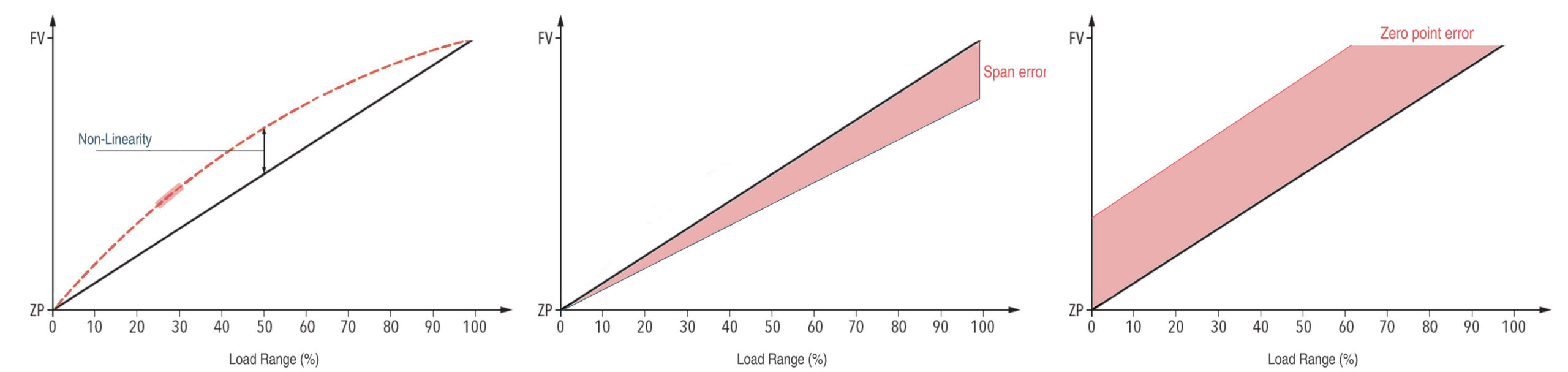
What is the difference between span error and zero error
Span error represents the percentage deviation of the sensor’s actual output span from the ideal specified span. It captures non-idealities over the full sensor range.
Zero error captures the non-ideality only at the sensor’s zero pressure point. It indicates how much the zero output deviates from the specified value.
Both errors affect the sensor’s overall accuracy, with zero error mainly affecting measurements near zero pressure, and span error affecting measurements across the full pressure range.
How do manufacturers make sure span error as low as possible
Span error refers to the deviation of a pressure sensor’s actual output span from its specified ideal span, span error affects measurement across the full pressure range. In order to improve the measurement accuracy, there are a few ways to minimize span error in pressure sensor design and fabrication:
1. Use high-precision components
Many factors can cause span error, but one major factor is tolerances and mismatches in the sensor’s electronic components like resistors, capacitors, transistors, etc.
The tolerances specify how much the actual component value can differ from the rated value. Wider tolerances mean higher uncertainties in the component values.
For example, two 1k ohm resistors with 5% tolerance are used in a Wheatstone bridge pressure sensor circuit. This means the actual resistance of the resistors can be anywhere between 950 ohm to 1050 ohm.
Even if the nominal resistance is the same, due to the 5% tolerance, there is a chance the two resistors will have slightly different values. This mismatch can cause the bridge to become unbalanced, introducing span error.
However, if we use 1k ohm resistors with 0.1% tolerance instead, the actual resistances will be between 995 ohm to 1005 ohm. There is much less chance of a mismatch between the two resistors.
This will reduce the component-induced span error in the sensor. The smaller the tolerance, the lower the span error caused by component mismatches.
2. Reduce non-linearity
For various reasons, most sensors exhibit some degree of non-linearity. The output may not change at a perfectly constant rate across the full input range. This can distort the sensor’s actual output span.
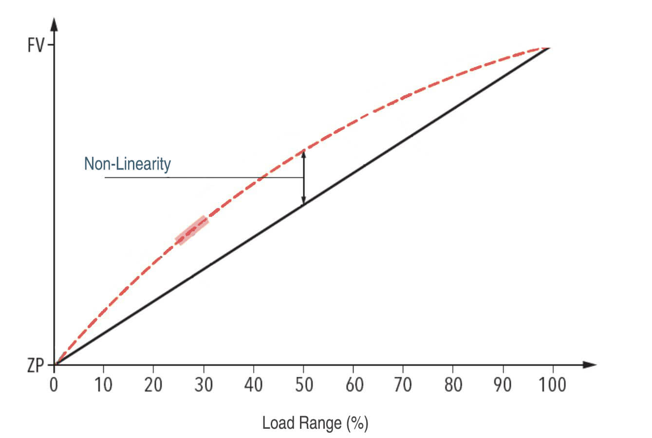
For example, a pressure sensor is specified to output 1-5 volts as the input pressure changes from 0-100 PSI. The ideal span is 5-1 = 4 volts.
But due to non-linearity, the sensor’s output may change very slowly at lower pressures, then increase more quickly at higher pressures. This can cause the actual output span to be greater than 4 volts, introducing positive span error.
We need to minimize the sensor’s non-linearity to reduce this span error. There are a few ways to do this:
Use a sensing element with high inherent linearity, like a piezoresistive silicon sensor.
Perform linearity corrections using algorithms or look-up tables to linearize the sensor output electronically.
Tune the sensor’s mechanical and electrical design to achieve high linearity. For example, optimize the proof mass, transducer design, etc.
Perform multi-point calibration to characterize and compensate for non-linearities in the sensor response.
The lower the sensor’s non-linearity, its actual output span will be closer to the ideal specified span. This reduces span error and improves the sensor’s accuracy.
3. Perform calibration
Even with high-precision components and designs to minimize non-linearity, some span error is unavoidable in real sensors due to physical limitations and variations.
This is where calibration comes in. We can characterize the sensor’s actual span error by performing a 2-point or multi-point calibration of the sensor using precision pressure sources and measurement equipment.
Then by applying appropriate corrections or adjustments, we can electronically compensate for the span error and make the sensor’s actual output match the specified ideal output.
For example, let’s say a pressure sensor has a positive span error of 2%. During calibration:
- We apply 0 PSI and measure the sensor’s zero output, say 1 volt.
- We apply 100 PSI and measure the sensor’s full scale output, say 5.2 volts instead of the ideal 5 volts.
- We calculate the sensor’s actual span as 5.2-1 = 4.2 volts, resulting in a 2% positive span error.
- We then apply an electronic correction to scale down the sensor’s full scale output by 2%, bringing it back to the ideal 5 volts.
- Now the sensor’s actual output span matches the specified ideal span of 4 volts, eliminating the span error.
4. Perform temperature compensation
One factor that can cause span error is temperature changes. As temperature varies, it can shift the sensor’s zero pressure output and full-scale output. This shift in the two endpoints changes the sensor’s actual output span.
For example, let’s say a sensor is specified to output 1-5 volts as the pressure changes from 0-100 PSI. The ideal span is 5-1 = 4 volts.
But as temperature increases, the sensor’s zero pressure output may increase from 1 volt to 1.025 volts. And its full-scale output may increase from 5 volts to 5.1 volts.
This gives an actual span of 5.1-1.025 = 3.975 volts. Since the ideal span is 4 volts, a negative span error is around 0.6%.
To compensate for this temperature-induced span error, we can perform temperature compensation using either:
Active compensation circuits monitor the sensor’s temperature and electronically adjust the output to negate the temperature effects.
Passive compensation uses temperature-sensitive elements like thermistors that self-correct the span drift over temperature.
Multi-point temperature calibration to characterize the span variation with respect to temperature. The data is then used to scale the output accordingly electronically.
By performing effective temperature compensation, we can keep the sensor’s actual output span close to the ideal specified span over the full operating temperature range. This minimizes temperature-induced span error.
5. Reduce hysteresis
Hysteresis refers to the phenomenon where a pressure sensor gives different readings for the same pressure, depending on the direction from which that pressure is approached.
For example, when the pressure is increased from 0 to 100 PSI, the sensor may output 1 to 5 volts. But when the pressure is decreased from 100 to 0 PSI, the sensor may output 1 to 4.8 volts. This difference in the output span in the two directions is known as hysteresis.
The presence of hysteresis in a sensor can introduce span error. This is because the sensor’s specified ideal span does not consider hysteresis. It assumes the same output span will be obtained irrespective of the pressure direction.
The specified ideal span for the above example sensor is 5-1 = 4 volts. But the actual output span obtained when decreasing the pressure is 4.8-1 = 3.8 volts. This represents a negative span error of around 5%.
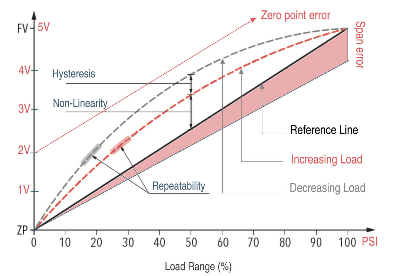
So hysteresis in a sensor reduces its actual output span compared to the specified ideal span, introducing span error.
We need to reduce the hysteresis in the sensor’s design and fabrication to minimize this effect. Ways to achieve this include:
- Using low hysteresis sensing elements and transducer materials
- Optimizing the proof mass and housing to minimize stiction and friction effects
- Performing stress relief and conditioning procedures to break in the sensor
- Applying lubricants or coatings to reduce hysteresis
- Performing compensation using data from hysteresis characterization tests
The lower the hysteresis in the sensor, the closer its actual output span will be when the pressure is increased or decreased. This minimizes span error due to hysteresis.
6. Isolate the sensing element
By properly isolating the pressure sensor’s sensing element through appropriate housings, mounts, etc., we can minimize the influence of environmental factors that can introduce span error. This allows the sensor to provide an output span that more closely matches the ideal specified span, resulting in lower overall span error.
For example, let’s consider temperature effects:
Specifications:
- Pressure range: 0-100 PSI
- Ideal output span: 5-1 = 4 V
Without isolation:
- At 25°C, output at 0 PSI = 1 V and at 100 PSI = 5 V
- Actual span = 5-1 = 4 V, so 0% span error
- At 100°C, output at 0 PSI = 1.1 V and at 100 PSI = 5.2 V
- Actual span = 5.2-1.1 = 4.1 V, so positive span error of 2.5%
The temperature change caused the sensing element to shift its zero and full scale outputs, changing the actual output span and introducing span error.
With proper isolation:
- The temperature change has less effect on the sensing element
- Actual span stays around 4 V at both 25°C and 100°C
- Lower span error over the temperature range