Introduction
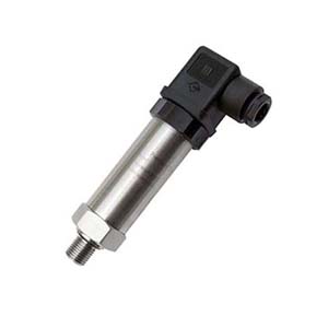
A digital pressure sensor is a device that measures and detects the pressure of a fluid or gas and converts it into a digital signal for further processing or display. It typically consists of a sensing element, which can be a piezoresistive, capacitive, or piezoelectric element, and an electronic circuitry that converts the analog pressure measurement into a digital output.
The digital signal can then be transmitted to a computer, microcontroller, or other electronic devices for monitoring, control, or analysis.
Digital pressure sensors are the devices that convert physical pressure into a digital signal that can be interpreted by electronic systems. They are integral components in various applications across industries, including automotive, aerospace, medical, HVAC, and industrial process control.
In this guide, we will discuss the most popular type of digital output for pressure sensor, you will find the highlight features including SPI, I2C, RS485 and CAN Bus protocols, for details content, you can also browse our exact blog pages.
Technical Specifications of digital pressure sensor
Pressure Range: The pressure range indicates the minimum and maximum pressure that the sensor can accurately measure.
For example, a sensor might have a range from 0 to 100 PSI (pounds per square inch), or from -15 to 15 PSI for differential pressure applications.
This indicates how closely the sensor’s measurements match the true pressure. It’s usually expressed as a percentage of full scale (FS), such as ±0.25% FS. This means that if a sensor has a range of 0 to 100 PSI, the readings can deviate by as much as ±0.25 PSI from the actual pressure.
The smallest change in pressure that the sensor can detect. For a high-resolution sensor, this might be as small as 0.001 PSI.
Output Interface
The type of digital protocol used to communicate with the sensor. Common types are I2C and SPI, which are serial communication protocols used for short-distance, intra-board communication.
How digital pressure sensor work
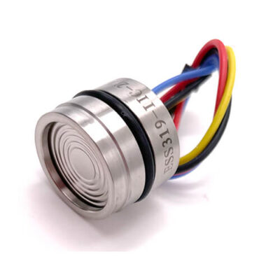
Digital output pressure sensors typically contain a piezoresistive element, a type of resistor that changes its resistance based on the pressure applied to it. This resistance change is converted into a voltage change by a circuit within the sensor.
This analog voltage signal is then converted into a digital signal by an Analog to Digital Converter (ADC). The ADC resolution, often 12, 16, 24 or even 32 bits, determines the smallest pressure change that can be detected by the sensor.
The digital signal is then sent to a microcontroller or other digital system using a digital communication protocol. The receiving system uses this digital signal to determine the pressure based on calibration data provided by the sensor manufacturer.
Advantages of digital output signal
1, Reliability
Digital signals are less susceptible to noise and interference than analog signals, which can improve the reliability of the pressure readings, especially over long distances or in noisy environments.
2, Integration
Digital sensors are easier to integrate with other digital systems, as they can communicate directly with microcontrollers and microprocessors.
3, Calibration
Many digital pressure sensors have built-in temperature compensation and calibration data, which can improve accuracy across a wide range of operating conditions.
4, Programmability
Some digital pressure sensors allow users to program the pressure range, output data rate, and other parameters, providing flexibility for different applications.
Types of digital pressure sensor
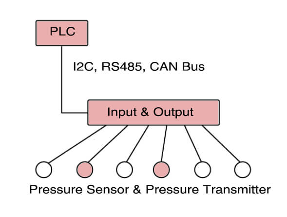
Digital pressure sensors are commonly used in various applications such as industrial automation, automotive systems, medical devices, and consumer electronics.
Here are some common types of digital interfaces for pressure sensors that Eastsensor produce, also the most regular types with different speed and range from short distance to very long remote data transmit.
1, I2C (Inter-Integrated Circuit) Sensors:
These sensors use the I2C protocol, a serial communication protocol allowing multiple devices to communicate with each other over the same bus.
2, SPI (Serial Peripheral Interface) Sensors:
These sensors use the SPI protocol, another type of serial communication protocol known for its high speed.
3, CAN (Controller Area Network) Sensors:
These sensors use the CAN protocol, a robust communication protocol often used in automotive applications.
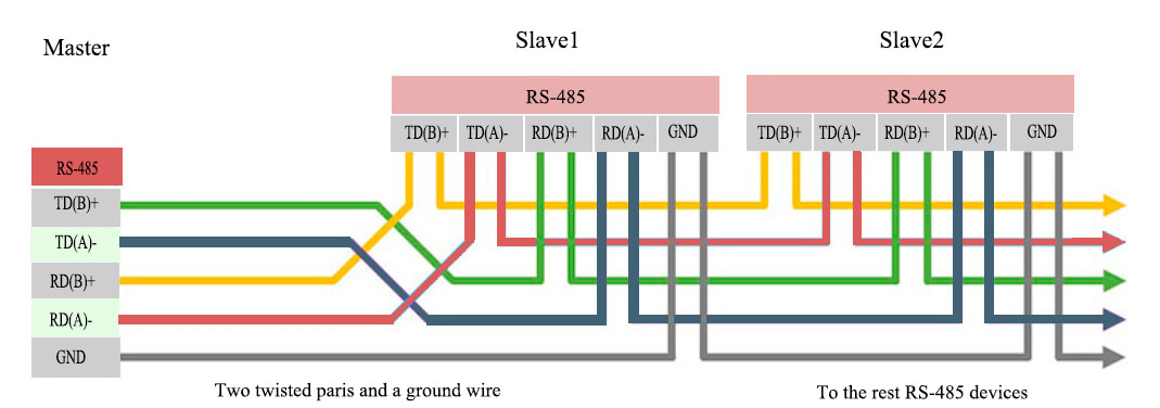
RS485 is a standard for serial communication transmission of data. It uses differential signaling, which means it transmits information using two complementary signals. This allows it to reject common-mode noise, making it robust in industrial environments.
5, 4-20mA HART
The 4-20mA signal is a standard in many industries for analog signals over long distances.
HART (Highway Addressable Remote Transducer) is a protocol that can be used in conjunction with the 4-20mA standard. It allows for two-way field communication, meaning it can transmit and receive more than one signal over the same wires.
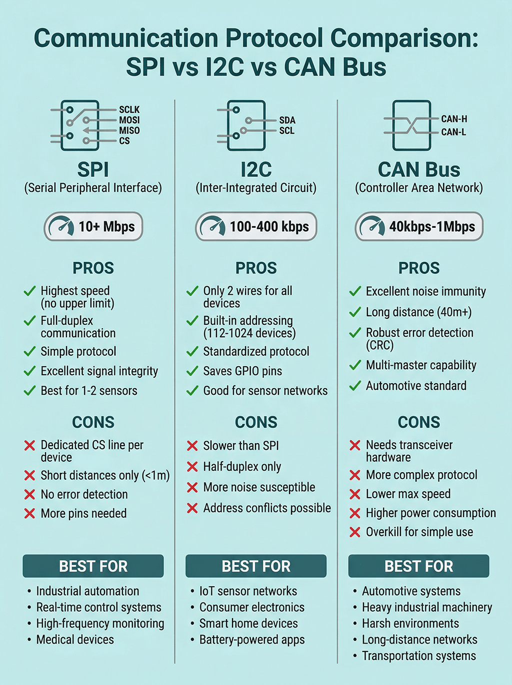
What is the advantage and trade-off of each type?
I2C (Inter-Integrated Circuit):
- Speed/Max Bit Rate: Standard mode up to 100 kbit/s, Fast mode up to 400 kbit/s, and High-Speed mode up to 3.4 Mbit/s.
- Number of Pins: 2 (SDA for data, SCL for clock).
- Data Transfer Distance: Typically less than 1 meter.
- Noise Immunity: Moderate due to voltage level signaling.
- Inter-Connectivity: Can connect multiple devices (both masters and slaves) on the same bus.
- Typical Application: Short-distance, intra-board communication.
- Pros: Simplicity, flexibility with multiple masters and slaves, and built-in addressing.
- Cons: Limited distance and speed, no error checking.
SPI (Serial Peripheral Interface):
- Speed/Max Bit Rate: Typically up to 10 Mbit/s, can be higher depending on the specific device.
- Number of Pins: 4 (MISO, MOSI, SCK, and SS).
- Data Transfer Distance: Typically short, within a single circuit board.
- Noise Immunity: Low, due to the absence of differential signaling.
- Inter-Connectivity: Single master with multiple slaves using separate chip select lines.
- Typical Application: Short-distance, high-speed applications.
- Pros: High speed, full duplex communication.
- Cons: Requires more pins than I2C, not suitable for long distance, no error checking.
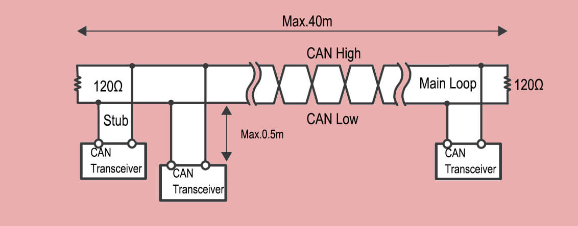
CAN (Controller Area Network):
- Speed/Max Bit Rate: Up to 1 Mbit/s at short distances, lower at long distances.
- Number of Pins: 2 (CAN_H and CAN_L for differential signaling).
- Data Transfer Distance: Up to 40 meters at 1 Mbit/s, can be extended to 1 kilometer at lower speeds.
- Noise Immunity: High, due to differential signaling and error checking.
- Inter-Connectivity: Multiple devices on the same bus using message-based communication.
- Typical Application: Vehicle network (automotive), industrial automation.
- Pros: Robust error handling, excellent noise immunity, great for networking multiple devices.
- Cons: More complex than I2C or SPI, lower speed.
RS-485
- Speed/Max Bit Rate: Up to 10 Mbit/s.
- Number of Pins: 2 (A and B for differential signaling).
- Data Transfer Distance: Up to 1.2 kilometers.
- Noise Immunity: High, due to differential signaling.
- Inter-Connectivity: Multi-point systems, up to 32 devices on the same bus.
- Typical Application: Long-distance, noisy environments, industrial control systems.
- Pros: Long-distance capability, high speed, excellent noise immunity.
- Cons: Half-duplex, requires careful management of bus idle state, more complex than I2C or SPI.
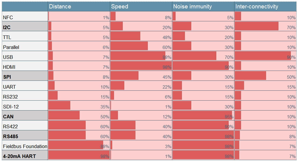
| Protocol | Distance | Speed/Max Bit Rate | Pins | Noise Immunity | Inter-Connectivity |
|---|---|---|---|---|---|
| NFC | Up to 0.1 m | Up to 424 kbit/s | N/A | Low | Point-to-point |
| I2C | Up to 2 m | Up to 3.4 Mbit/s | 2 | Moderate | Multi-master, multi-slave |
| TTL | Up to 2 m | Tens of Mbit/s | 1 per signal | Low | Depends on implementation |
| Parallel | Up to 3 m | Hundreds of Mbit/s | 20-50 | Moderate | Point-to-point |
| USB | Up to 5 m | Up to 20-40 Gbit/s | 4--24 | Very High | Point-to-point |
| HDMI | Up to 5 m | Up to 48 Gbit/s | 19 | Very High | Point-to-point |
| SPI | Up to a few meters | Up to 50 Mbit/s | 4 | Moderate | Single-master, multi-slave |
| UART | Up to 10 m | Up to 5 Mbit/s | 2 | Low | Point-to-point |
| RS232 | Up to 15 m | Up to 115.2 kbit/s | 9 | Low | Point-to-point |
| SDI-12 | Up to 100 m | 1200 bit/s | 3 | Moderate | Multi-drop |
| CAN | Up to 1000 m | Up to 1 Mbit/s | 2 | Very High | Multi-master |
| RS422 | Up to 1200 m | Up to 10 Mbit/s | 4 | High | Point-to-point, multi-drop |
| RS485 | Up to 1200 m | Up to 10 Mbit/s | 2 or 4 | Very High | Multi-drop |
| Fieldbus Foundation | Up to 1900 m | Up to 31.25 kbit/s | 2 | Very High | Multi-drop |
| 4-20mA HART | Up to 2000 m | 1200 bit/s | 2 | Very High | Multi-drop |
Which is best for automotive industry?
In automotive applications, the Controller Area Network (CAN) bus protocol is widely recognized as the best choice for sensor output communication. This assertion is based on several technical specifications and the requirements of automotive systems:
- Reliability
- Multi-Device Communication
- Error Checking
- Real-Time Capability
- Standardization
- Click to check details of: CAN Bus Pressure Sensor
While CAN bus is the standard, other communication protocols can also be used in automotive applications.
For example, Local Interconnect Network (LIN) may be used for less critical systems due to its lower cost, and FlexRay may be used in systems requiring higher data rates or deterministic behavior.
Ethernet (via BroadR-Reach or Automotive Ethernet) is also becoming more popular in vehicles, especially for high-bandwidth applications like infotainment systems or advanced driver-assistance systems (ADAS).
In terms of sensor output, while digital protocols like CAN are often preferred for their noise immunity and integration with digital systems, analog sensors (like those using the 0.5-4.5V or 4-20mA standards) can still be used in certain automotive applications, where the simplicity and lower cost of analog sensors can be beneficial.
However, these are typically used in less critical systems and are increasingly being replaced by digital sensors.
Which is commonly used in industry control system?
In industrial control systems, a variety of digital output protocols are used for pressure sensors. The choice of protocol often depends on the specific requirements of the system, such as the need for long-distance transmission, networking capabilities, or resistance to electrical noise.
1. Modbus:
Modbus is a serial communication protocol commonly used for connecting industrial electronic devices. It’s simple, robust, and allows for communication between many devices over long distances, making it a popular choice for industrial applications.
2. HART (Highway Addressable Remote Transducer): HART is a widely used communication protocol in process industries. It’s designed to superimpose digital communication signals onto the traditional 4-20mA analog signal used in these industries, allowing for two-way field communication and enabling additional features like device configuration and diagnostics.
Here are some key points about 4-20mA HART:
- HART can send digital data over the same wires as the 4-20mA analog signal. This allows for additional information beyond just the primary sensor reading to be transmitted, such as device status, diagnostics, or additional sensor readings.
- HART communication can support up to two masters (e.g., a handheld device for field configuration and a control system) and multiple slaves (the field devices).
- It is widely used in process control industries for field device communication, enabling configuration, calibration, and diagnostics.
3. Profibus:
Profibus (Process Field Bus) is another common protocol in process automation industries. It provides high-speed communication and supports a wide range of devices, from simple field devices to complex automation systems.
4. CAN (Controller Area Network): While it’s best known for its use in automotive applications, CAN is also used in some industrial control systems, especially in machine control where a real-time response is required.
5. Zigbee: Zigbee is a high-level communication protocol used to create personal area networks with small, low-power digital radios. It’s often used in wireless pressure sensors in applications such as home automation, medical device data collection, and other low-power, low-bandwidth needs.
Click to download datasheet of: EST345Z-Zigbee Wireless Pressure Transmitter
Which is for low-speed communication between sensor and computer?
For low-speed communication between a sensor and a computer, the I²C (Inter-Integrated Circuit) and SPI (Serial Peripheral Interface) protocols are commonly used.
Both are synchronous serial communication protocols developed for short-distance, low-speed communication between integrated circuits.
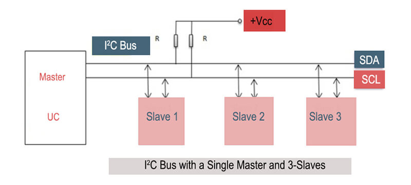
I²C
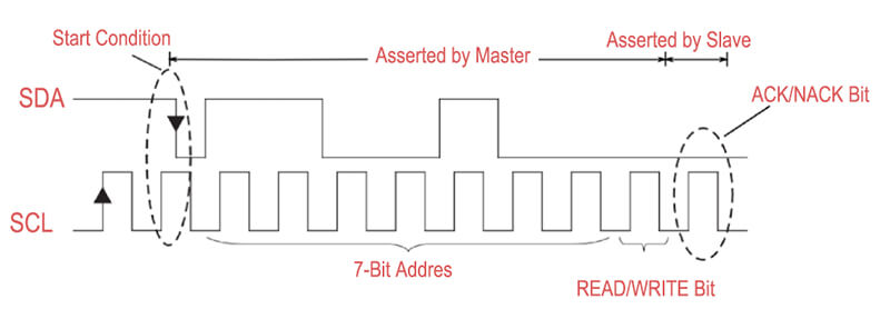
- I²C is a two-wire interface, using one wire for data (SDA) and one for clock (SCL).
- It supports multiple master and slave devices on the same bus.
- It is typically used for lower speed applications (standard modes support up to 100 kbit/s and 400 kbit/s, but a high-speed mode can support up to 3.4 Mbit/s).
- It includes built-in support for addressing and acknowledgement, simplifying communication between devices.
- It is often used for connecting peripheral hardware to a microcontroller, such as sensors, display drivers, or memory chips.
SPI
- SPI uses a four-wire interface, with separate wires for data in (MISO), data out (MOSI), clock (SCK), and a chip select line for each slave (SS).
- It only supports one master device but can support multiple slaves.
- It can generally support higher speeds than I²C (up to several Mbit/s), but the actual speed is determined by the master device and the length and quality of the connections.
- It doesn’t include built-in addressing or acknowledgement, making the protocol simpler but requiring additional handling in software if these features are needed.
- Like I²C, it is often used for connecting peripheral hardware to a microcontroller.