Pressure Sensor Power Supply
When your pressure measurement system fails at 2 AM, the culprit is often not the sensor itself—it’s the power supply. I’ve seen engineers waste weeks troubleshooting signal drift, only to discover they paired a voltage-output sensor with a current-source power supply.
Let’s cut through the confusion. This guide breaks down everything you need to know about pressure sensor power supplies, based on real-world applications and field experience.
Why Your Power Supply Choice Actually Matters
In our daily life, it really exists the fact that most specification sheets won’t tell you:
The wrong power supply doesn’t just mean your sensor won’t work. It means unstable readings, premature failure, and mysterious system behavior that’ll have you questioning your engineering degree.
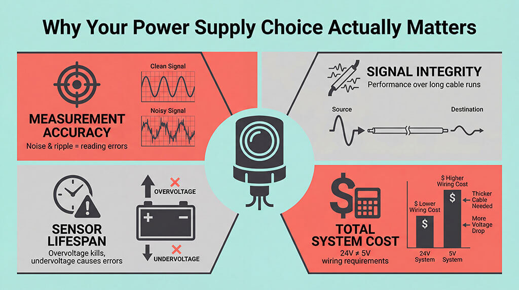
Your power supply affect:
- Measurement accuracy (noise and ripple translate directly to reading errors)
- Signal integrity over long cable runs
- Sensor lifespan (overvoltage kills components, undervoltage causes erratic behavior)
- Total system cost (24V systems need different wiring than 5V systems)
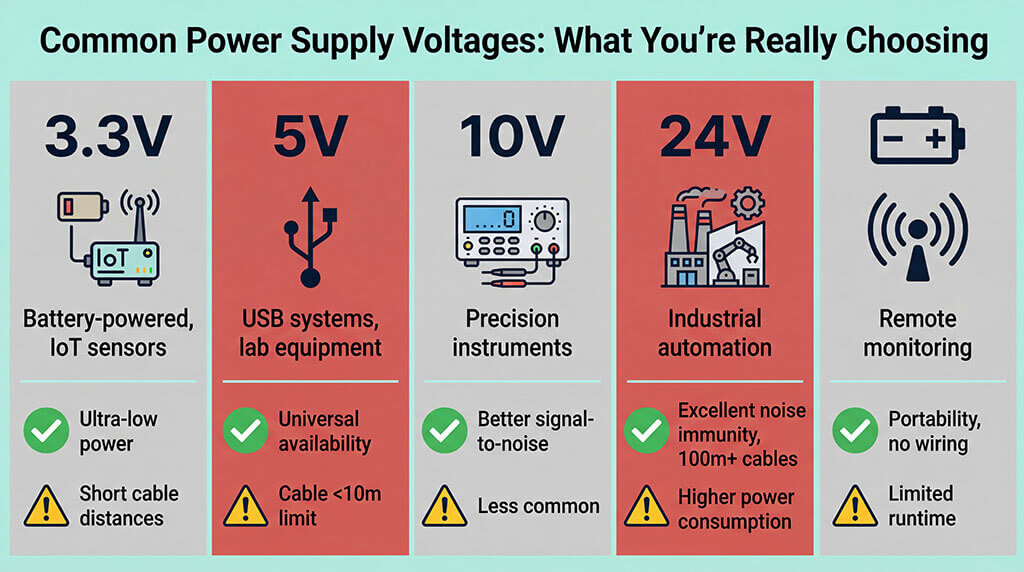
Common Power Supply Voltages: What You’re Really Choosing
Voltage Typical Applications Key Advantages Watch Out For
3.3V Battery-powered devices, IoT sensors, I2C output sensor and instruments Ultra-low power consumption, direct battery compatibility, modern MCU interface Limited output signal range, shorter cable distances, sensitivity to voltage drop
5V USB-powered systems, consumer electronics, lab equipment Universal availability, USB compatibility, works with most microcontrollers Cable length limitations (typically <10m), voltage drop concerns with cheap cables
10V Precision industrial instruments, laboratory measurement Better signal-to-noise ratio than 5V, good for ratiometric outputs Less common in modern designs, requires special power supplies
24V Industrial automation, process control, factory floor Excellent noise immunity, works over long distances (100m+), industry standard Higher power consumption, needs voltage regulation for electronics
Battery Remote monitoring, field instruments, wireless nodes Portability, installation flexibility, no wiring infrastructure needed Limited operating time, voltage varies with charge state, temperature sensitivity
The Real-World Breakdown
Choose 3.3V when: you’re building battery-powered remote monitoring, wireless sensor networks, digital output (ie. I2C output) or anything that needs to run for months on a coin cell. Your sensor needs to sip power, not gulp it.
Choose 5V when: you’re integrating with computers, development boards, or existing USB infrastructure, or you need ratio-metric output (i.e 0.5-4.5V output) It’s the sweet spot for bench testing and prototyping. Just don’t run long cables without buffering (less than 10m is recommended).
Choose 24V when: you’re installing sensors in factories, refineries, or anywhere cables run through conduit alongside motor drives and VFDs. The extra voltage headroom fights off electrical noise that would destroy a 5V signal.
Choose battery power when: trenching for power cables costs more than your entire sensor budget, or when your application is temporary, mobile, or in hazardous areas where running mains power requires expensive certification.
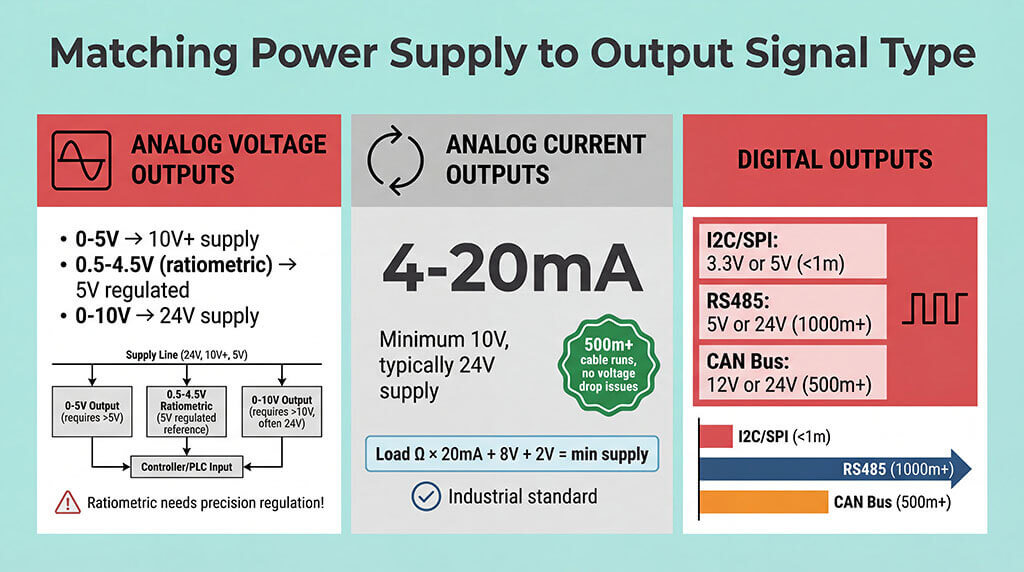
Matching Power Supply to Output Signal Type
Your sensor’s output signal type and its power supply requirements are connected but not identical. This is where engineers get tripped up usually.
Analog Voltage Outputs
Output Type Recommended Power Supply Why It Matters
0-5V 10V or higher Sensor needs headroom above output range for internal circuitry
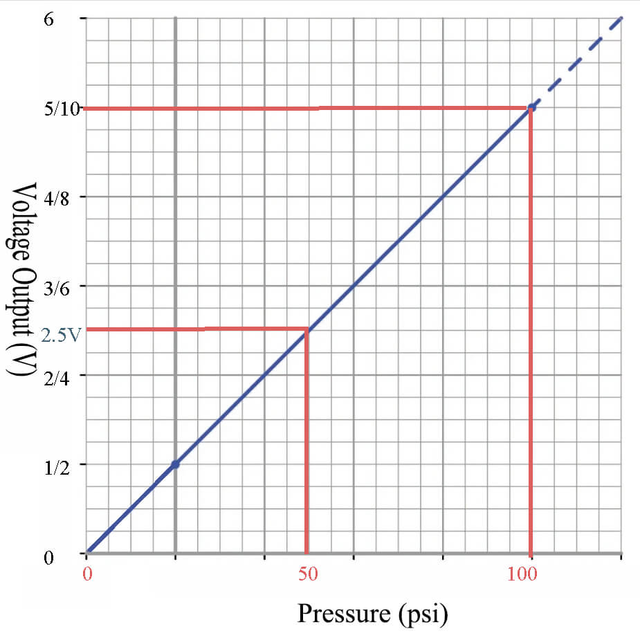
0.5-4.5V (ratiometric) 5V regulated Output is proportional to supply voltage—tight regulation essential
1-5V 10V or 24V Avoids issues with ground offset and provides cleaner zero-point
0-10V 24V Industrial standard, requires higher supply for amplification stages
Ratiometric outputs deserve special attention. When your datasheet says “0.5-4.5V output from 5V supply,” it means the output is a percentage of the supply voltage. If your supply drops to 4.8V, your full-scale reading becomes 4.32V instead of 4.5V. Use a precision voltage regulator (0.1% tolerance or better), not whatever wall adapter you found in the drawer.
Analog Current Outputs
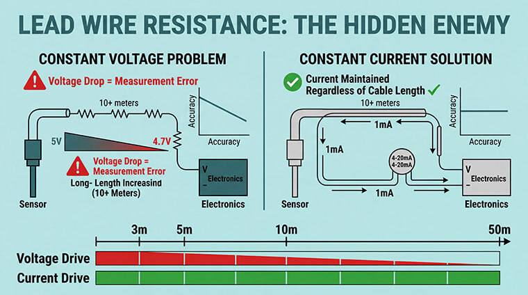
4-20mA loops revolutionized industrial measurement for good reason. The current doesn’t care about cable resistance, connection corrosion, or voltage drops. You can run 500 meters of wire and still get perfect readings.
These sensors need minimum 10V, typically 24V supply.
Here’s why: the sensor must generate enough voltage to push current through your load resistor AND power its internal electronics. The math is simple but unforgiving.
Calculate minimum supply voltage:
- Load resistance × 20mA + sensor voltage drop + safety margin
- Example: (250Ω × 0.02A) + 8V + 2V = 15V minimum
- Use 24V for real-world reliability
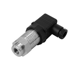
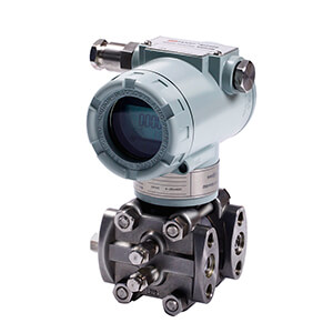
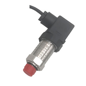
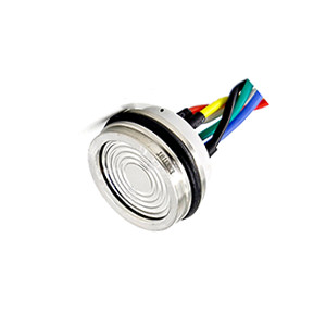
| 4-20mA Pressure Sensor | 0.5-4.5V Pressure Sensor |
Digital Outputs (I2C, SPI, RS485, CAN Bus)
| Interface | Typical Supply | Cable Length | Why This Matters |
|---|---|---|---|
| I2C | 3.3V or 5V | <1m practical | Simple two-wire, perfect for PCB-level integration, dies quickly with noise |
| SPI | 3.3V or 5V | <1m | Fastest for high-speed data logging, multiple wires = multiple failure points |
| RS485 | 5V or 24V | 1000m+ | Differential signaling kills noise, industrial workhorse, needs termination |
| CAN Bus | 12V or 24V | 500m+ | Automotive/mobile equipment standard, sophisticated error handling, overkill for simple setups |
The power supply voltage for digital sensors often runs double duty: powering the sensor AND defining the logic levels. Mixing 3.3V and 5V logic requires level shifters—don’t learn this the hard way by releasing smoke from expensive chips.
RS485 and CAN Bus sensors in industrial environments typically run on 24V because you’re often powering multiple sensors on the same supply lines. The higher voltage provides regulation headroom when voltage drops along the cable run.
Constant Voltage vs. Constant Current: The Truth Nobody Tells You
Most engineers ask “which is better?” Wrong question. Ask “which does my sensor need?”
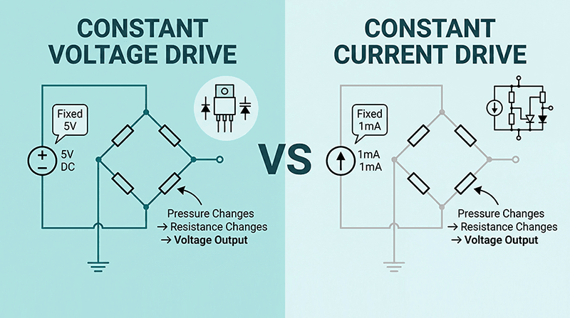
Constant Voltage Power Supplies
These maintain fixed voltage regardless of current draw. Think of every wall adapter, USB port, and battery you’ve ever used.
You need constant voltage when:
- Your sensor has voltage-output (0-5V, 0-10V, ratiometric)
- You’re using digital communication (I2C, SPI, RS485, CAN)
- The sensor includes internal regulation
- You’re powering multiple sensors from one supply
Critical specs to check:
- Regulation: 0.5% or better for ratiometric sensors
- Ripple: <50mV peak-to-peak (preferably <10mV for precision work)
- Load regulation: voltage shouldn’t sag when sensor draws peak current
Constant Current Power Supplies
These maintain fixed current regardless of voltage (within limits). Specialized and less common.
You need constant current when:
- Honestly? Almost never for pressure sensors.
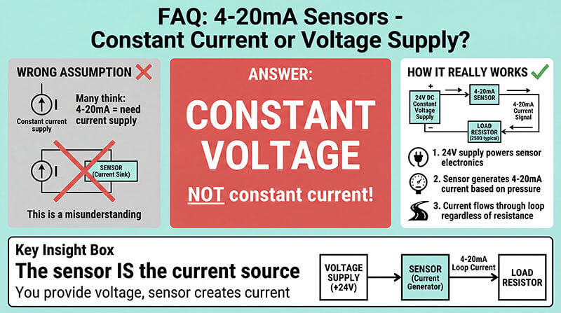
Here’s the confusion: 4-20mA sensors don’t need constant current supplies. They generate the current themselves. You need a constant voltage supply to power them, then measure the current they produce across a load resistor.
The only exception is if you’re designing the sensor itself and need to test current output stages during R&D. But that’s engineering the sensor, not using it.
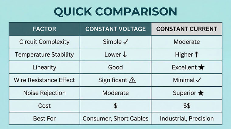
| Constant Voltage vs Constant Current |
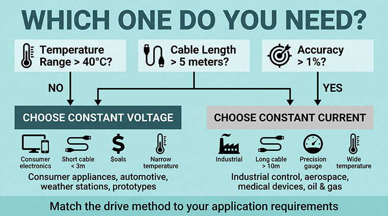
- You’re building prototypes or low-volume projects
- Operating temperature range is narrow (±20°C from room temperature)
- Cable runs are short (under 3 meters)
- Cost is the primary constraint
- You have clean, regulated power available
- Application examples: Consumer appliances, automotive cabin pressure monitoring, weather stations, hobby projects
- Temperature range exceeds 50°C span
- You need better than 0.5% accuracy
- Cable runs exceed 10 meters
- Operating in electrically noisy environments (motors, switching supplies nearby)
- Long-term stability is critical
- Application examples: Industrial process control, hydraulic systems, aerospace instrumentation, medical
Power Supply Quality: What Actually Affects Your Measurements
Two 24V power supplies aren’t created equal.
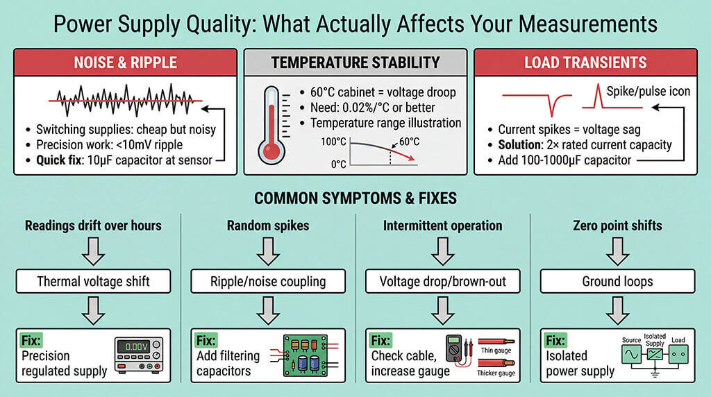
Noise and Ripple
Switching power supplies are cheap and efficient but noisy. That high-frequency switching noise couples into your sensor and appears as measurement jitter.
- For precision work (<0.1% accuracy): Use linear regulators close to the sensor or add aggressive filtering (ferrite beads + capacitors) to switching supplies.
- For industrial work (0.25-1% accuracy): Quality switching supplies work fine. Check the datasheet ripple spec—under 100mV peak-to-peak is acceptable.
- Quick fix for noisy power: Add a 10µF tantalum capacitor directly at the sensor power pins. Costs pennies, eliminates 80% of problems.
Voltage Stability Over Temperature
Your power supply sits in a control cabinet that reaches 60°C in summer. If it droops from 24.0V to 23.5V, your ratiometric sensor readings shift proportionally.
Look for temperature coefficient specs: 0.02%/°C or better for demanding applications.
Load Transients
When your sensor takes a pressure reading, current draw spikes briefly. A wimpy power supply voltage sags during this spike, causing measurement errors or crashes.
Solution: Use a power supply rated for at least 2× your sensor’s steady-state current draw. Add bulk capacitance (100-1000µF electrolytic) at the supply output.
Cable Distance: The Hidden Power Supply Variable
This trips up more projects than any other factor. Your sensor works perfectly on the bench with 1-meter wires. You install it 50 meters away and it behaves like garbage.
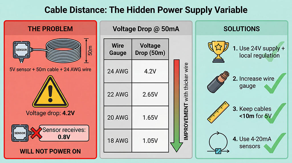
Voltage Drop Calculations
Wire Gauge Resistance Voltage Drop @ 50m Voltage Drop @ 100m
24 AWG 84 mΩ/m 4.2V @ 50mA 8.4V @ 50mA
22 AWG 53 mΩ/m 2.65V @ 50mA 5.3V @ 50mA
20 AWG 33 mΩ/m 1.65V @ 50mA 3.3V @ 50mA
18 AWG 21 mΩ/m 1.05V @ 50mA 2.1V @ 50mA
Round-trip distance (both power and return wires)
Reality check: Running a 5V sensor 50 meters on 24 AWG wire? Your sensor sees 0.8V (5V – 4.2V drop) if it draws 50mA. It won’t even power on.
Solutions in order of preference:
- Use 24V supply with local regulation at the sensor
- Increase wire gauge (thicker = less resistance)
- Keep cable runs under 10m for 5V systems
- Use current-loop (4-20mA) sensors for long distances
Special Considerations for Different Environments
Battery-Powered Applications
Battery voltage isn’t constant—it drops as the battery discharges. A “9V” battery starts at 9.5V when fresh and ends at 6V before you should replace it.
Design approaches:
- Use sensors with wide input voltage range (e.g., 6-30V operating range)
- Add boost or buck-boost converter for stable voltage
- Choose ultra-low-power sensors (<1mA) for long battery life
- Include low-battery detection to alert before unreliable readings
Battery life estimation:
- Battery capacity (mAh) ÷ average sensor current (mA) = runtime hours
- Example: 2000mAh battery ÷ 5mA sensor = 400 hours = 16.7 days continuous
- Add 30-50% safety margin for temperature effects and end-of-life voltage drop
Hazardous Areas (Intrinsically Safe)
Explosive atmospheres require intrinsically safe (IS) power supplies that limit energy to levels incapable of ignition. This isn’t optional—it’s code.
The barriers typically limit voltage to 28V and current to 93mA. Your sensor must be certified for the hazardous area classification (Class I Div 1, Zone 0, etc.).
Troubleshooting: When Your Power Supply Isn’t the Problem (Except It Is)
Symptom: Readings drift over hours
Power supply culprit: Thermal voltage shift or poor regulation
Fix: Upgrade to precision regulated supply or add local regulation
Symptom: Random spikes in readings
Power supply culprit: Ripple or electrical noise coupling
Fix: Add filtering capacitors close to sensor (10µF tantalum + 0.1µF ceramic)
Symptom: Sensor works intermittently
Power supply culprit: Voltage drop under load or brown-out
Fix: Check cable voltage drop, increase wire gauge or supply voltage
Symptom: Zero point shifts between installations
Power supply culprit: Ground loops or common-mode voltage
Fix: Use isolated power supply or differential input measurement
FAQ: Pressure Sensor Power Supply
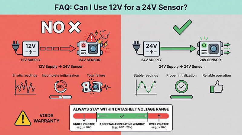
Can I use a 12V power supply for a 24V pressure sensor?
No. Undervoltage causes erratic readings, incomplete initialization, or total failure. Always stay within the datasheet’s specified voltage range. Using lower voltage voids warranty and risks equipment damage.
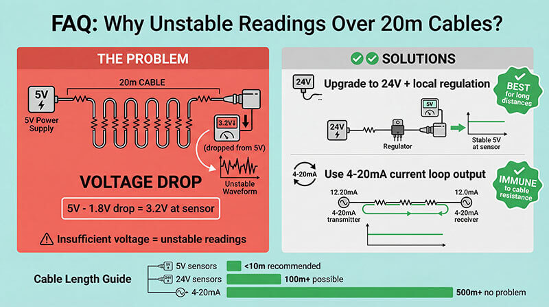
Why does my 5V sensor show unstable readings over 20-meter cables?
Voltage drop. 5V sensors lose significant voltage over long cables due to wire resistance. Solution: upgrade to 24V sensors with local regulation or use 4-20mA current loop output instead.
Do 4-20mA sensors need constant current or constant voltage power supplies?
Constant voltage. The sensor generates the current signal itself. You need a voltage supply (typically 24V) to power the sensor’s internal electronics, not to provide the current loop.
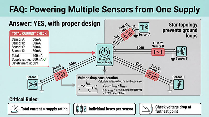
Can I power multiple pressure sensors from one power supply?
Yes, if total current draw stays below supply rating. Use individual fuses per sensor. Calculate voltage drop for furthest sensor. Star topology wiring prevents ground loop issues between sensors.
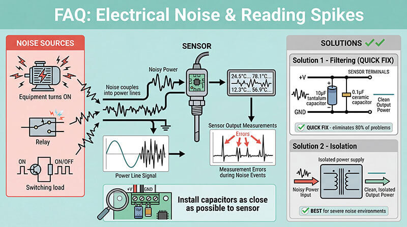
What causes my sensor readings to spike when nearby equipment turns on?
Electrical noise from motors, relays, or switching loads couples into your power lines. Add filtering capacitors (10µF tantalum + 0.1µF ceramic) directly at sensor terminals. Consider isolated power supply.
How do I know if my power supply ripple is too high?
Measure with oscilloscope at sensor terminals under load. For precision work, keep ripple under 10mV peak-to-peak. Industrial applications tolerate 50-100mV. Excessive ripple appears as measurement noise.
Why do battery-powered sensors give different readings as battery drains?
Ratiometric outputs change with supply voltage. Use sensors with built-in voltage regulation or add external buck/boost converter. Alternatively, choose sensors with absolute (non-ratiometric) outputs for battery applications.
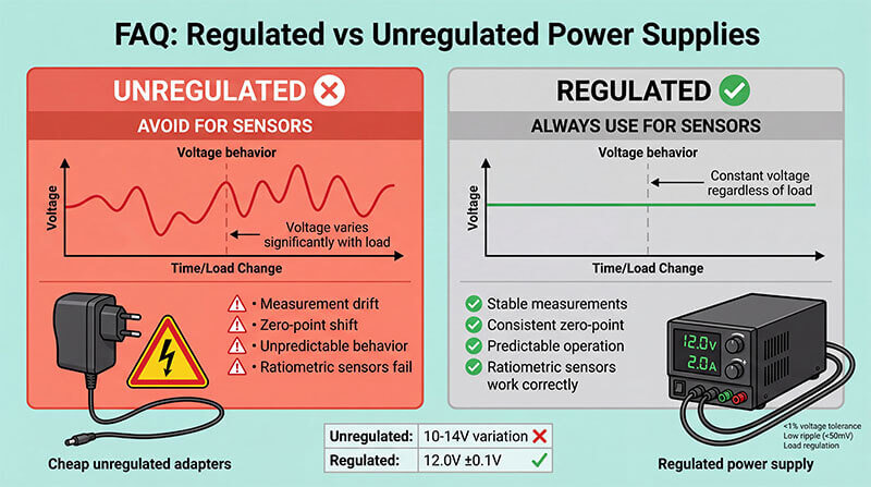
What's the difference between regulated and unregulated power supplies for sensors?
Regulated maintains constant voltage regardless of load; unregulated voltage varies significantly. Always use regulated supplies. Unregulated causes measurement drift, zero-point shift, and unpredictable behavior, especially with ratiometric sensors.
What We Provide: Power Supply Solutions That Work
We manufacture pressure sensors with carefully designed power supply requirements because we’ve seen what happens when things go wrong. Every sensor we ship includes:
- Wide input voltage ranges that tolerate real-world power supply variations
- Reverse polarity protection because everyone miswires something eventually
- Transient voltage suppression rated for industrial electrical environments
- Power supply recommendations specific to your output type and application
Whether you need a 3.3V I2C sensor for embedded systems or a 24V 4-20mA transmitter for factory floors, we engineer the power supply interface for reliability, not just minimum cost.
Still not sure which power supply configuration fits your application? Our engineering team reviews hundreds of pressure measurement systems every year. We’ll help you avoid the mistakes that delay projects and cost money.
Get Expert Guidance for Your Application
Contact our technical team today with your application details:
- Operating environment and cable distances
- Required accuracy and measurement range
- Integration requirements (analog vs digital)
- Quantity and timeline
We’ll recommend the optimal sensor and power supply configuration—or custom-design a solution if your application demands it.
Your pressure measurement system is only as reliable as its power supply. Let’s get it right the first time.