Pressure Sensor Types: 8 Pressure Sensors Comparison
Before we discuss the pressure sensor types, let’s take a look back at history.
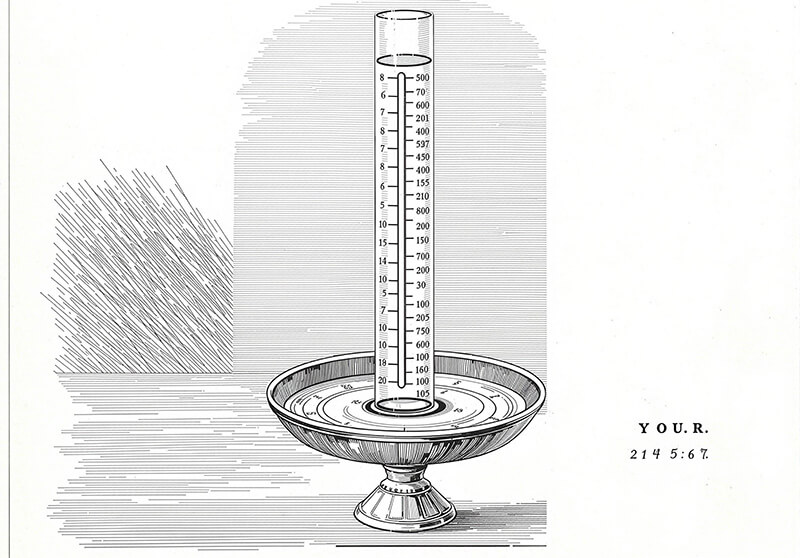
As early as the mid-1600s, people became deeply intrigued by the invisible force of pressure. The very first attempts to capture and measure it relied on simple glass tubes filled with liquids like mercury or water. By observing how much the fluid column rose or fell inside these tubes, experimenters could literally see the push and pull exerted by atmospheric pressure or other forces. These early barometers were the foundation, turning an unseen phenomenon into something visible and quantifiable.
Fast forward to today, we’ve moved far beyond tracking fluid levels in glass. We now harness the remarkable ways pressure alters materials – changing their shape, resistance, or even generating tiny electrical signals.
This deep understanding allows us to build incredibly sophisticated pressure sensors. Thanks to these miniature marvels, often etched onto silicon chips smaller than a fingernail, measuring pressure fluctuations has become an effortless feat of astounding precision and accuracy.
This invisible technology quietly ensures our car tires are safe, our weather forecasts are reliable, our medical devices function, and countless everyday systems operate smoothly. From watching mercury move in a tube to reading digital signals in an instant, our grasp of pressure has transformed the modern world
What is a pressure sensor?
Think about the invisible push of air around us, the squeeze of fluids in pipes, or the force deep underwater. A pressure sensor is our modern way of catching that invisible force and turning it into something we can see, measure, and use. It’s the clever successor to those early glass tubes where people watched liquid levels rise and fall.
Instead of relying on a moving column of mercury or water, today’s pressure sensors work their magic by sensing how pressure physically affects special materials inside them. When pressure pushes on these materials – whether it’s air, gas, liquid, or even a solid touch – it causes tiny, precise changes. It might bend a microscopic diaphragm ever so slightly, alter the electrical resistance of a wire, or make a crystal produce a tiny voltage.
These whisper-quiet reactions are then transformed into clear electrical signals. Sophisticated electronics instantly read these signals, translating the push of the invisible force into precise numbers we can understand on a screen or use to control a system. From keeping your car tires safe and your weather app accurate, to ensuring medical equipment delivers the right dose or your espresso machine brews perfectly, these unseen sentinels are constantly measuring the push and pull of our world, making the invisible, visible.
How pressure sensors work
No matter which Pressure Sensor Types, they work by detecting physical changes caused by pressure differences, then turning those changes into electric signals teams can use. This process gives real-time insights into equipment health. Here’s how it happens step by step:
Pressure physically changes a sensor component
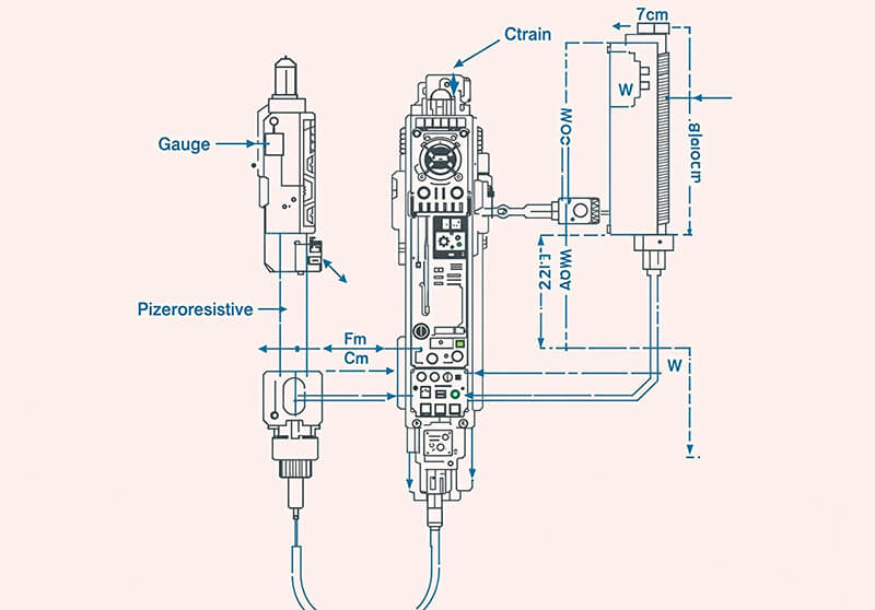
When pressure pushes against a sensor (like in a pipe or tank), it causes a tiny physical deformation. Most types of pressure sensors use a strain gauge – a sensitive component that stretches or compresses under pressure. This bending or flexing is the first key reaction the sensor measures.
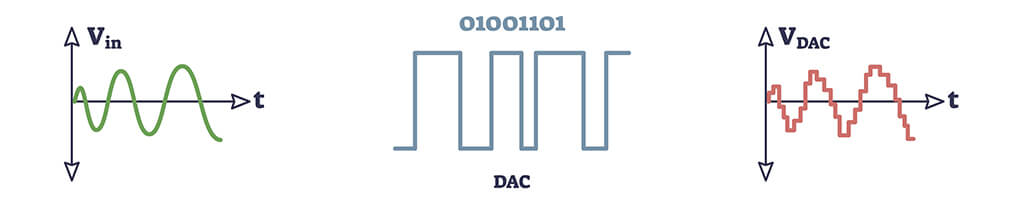
The physical change becomes an electrical signal
The strain gauge converts the physical deformation directly into an electrical signal. As it bends, its electrical resistance changes. This change in resistance creates a small voltage signal. The strength of this signal increases or decreases precisely based on how much pressure is applied.
The signal is sent as usable pressure data
This electrical signal now represents the actual pressure (in PSI, kPa, bar, etc.). The sensor sends this signal immediately to a PLC (Programmable Logic Controller). The PLC acts as the central brain of machinery or processes, collecting real-time data from sensors across the equipment or production line.
The PLC takes action based on the reading
With pressure data live in the PLC, it automatically responds if readings go outside set limits.
- High pressure: The PLC might trigger an alarm, shut down a pump, or open a relief valve to prevent equipment damage or rupture.
- Low pressure: It could signal a leak (e.g., in air lines or hydraulic systems), start a backup pump, or halt a process to avoid quality issues. This gives operators instant visibility and control over system conditions
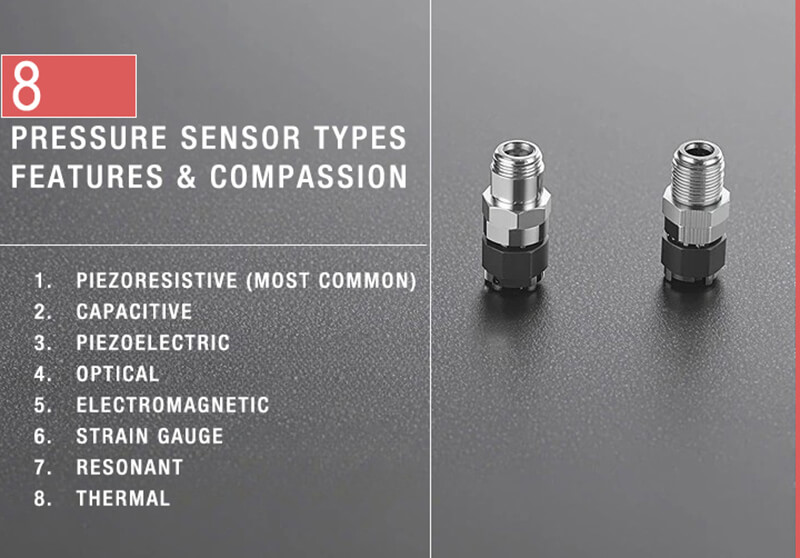
Pressure Sensor Types: 8 kinds of pressure sensors
Pressure sensors are classified based on their distinct mechanisms for detecting and measuring pressure changes, utilizing various physical principles to sense mechanical stress. Some of the most common Pressure Sensor Types are listed below:
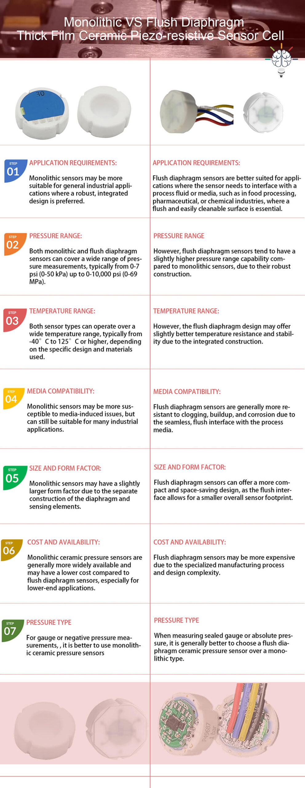
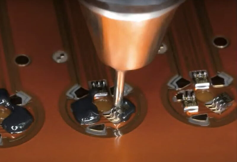
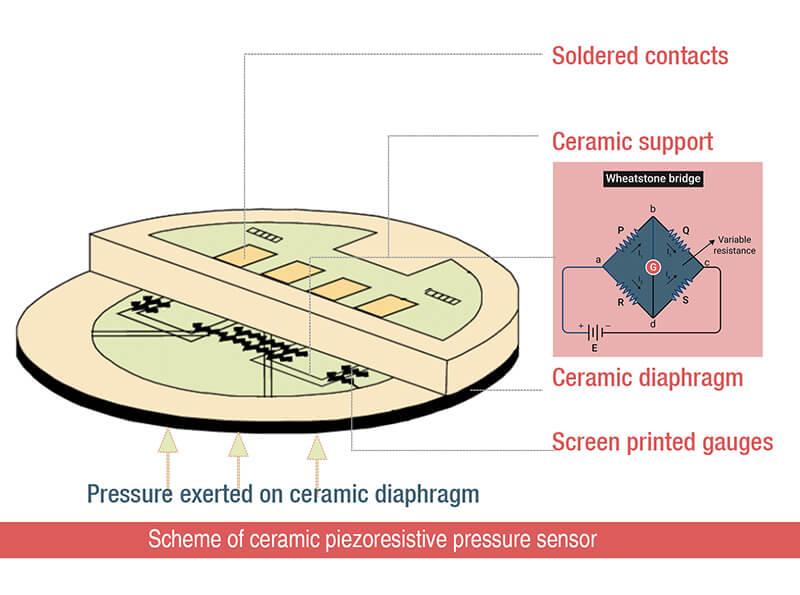
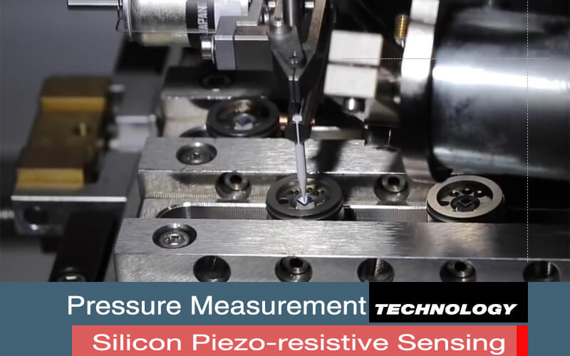
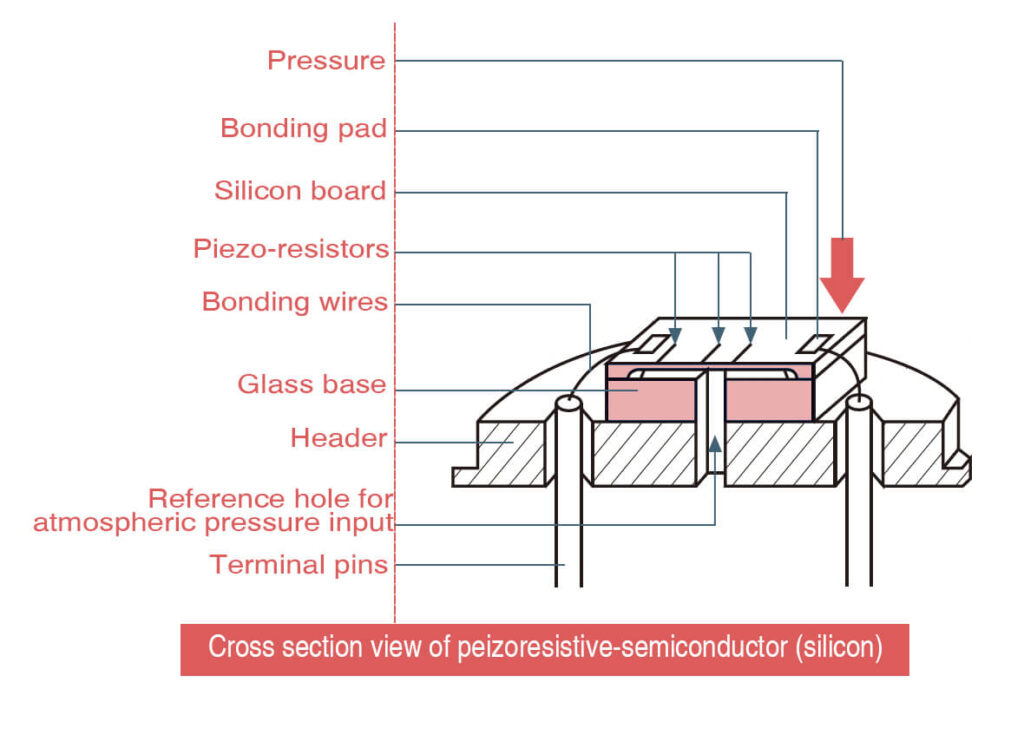
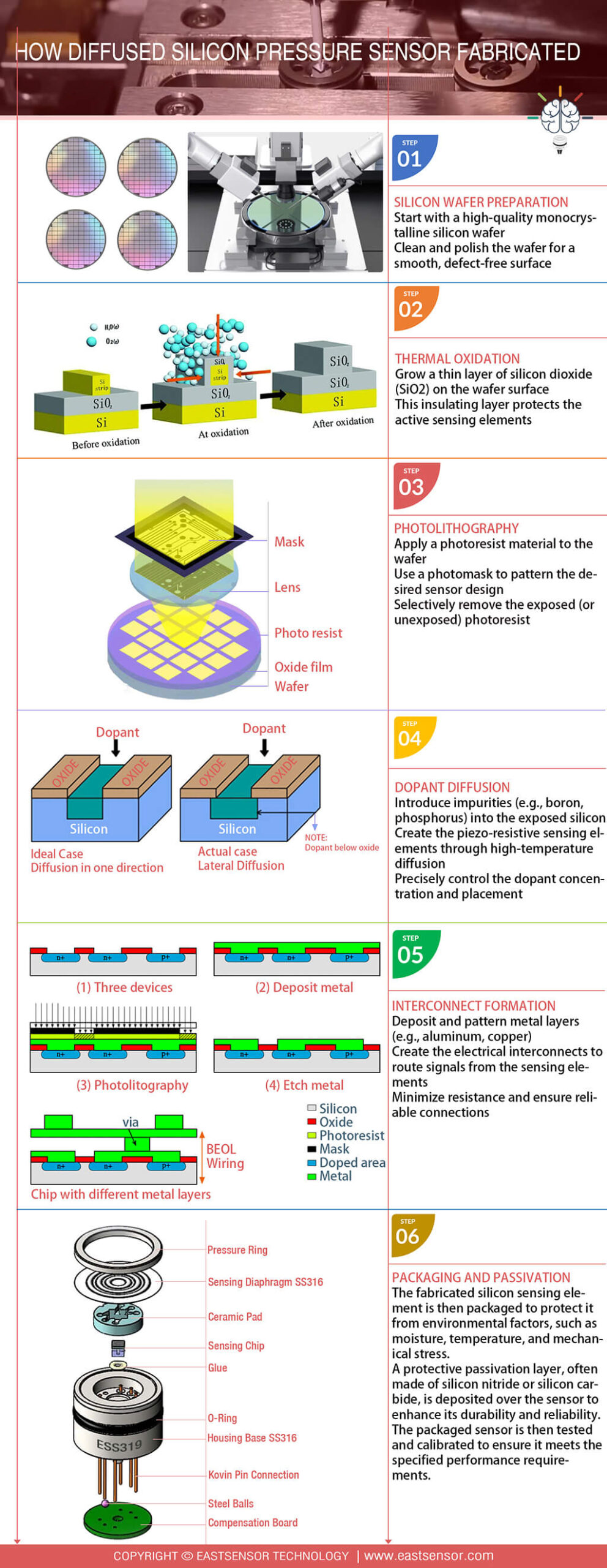
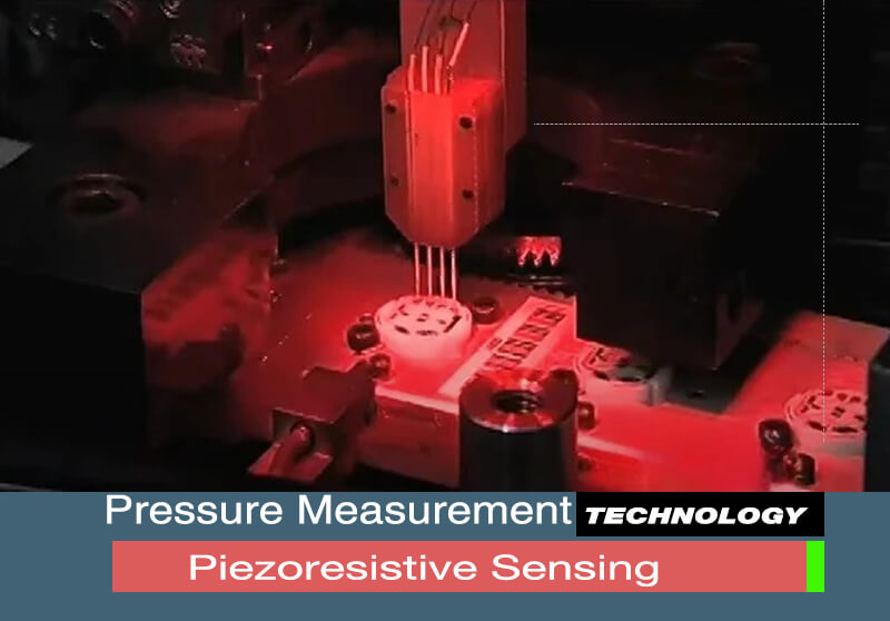
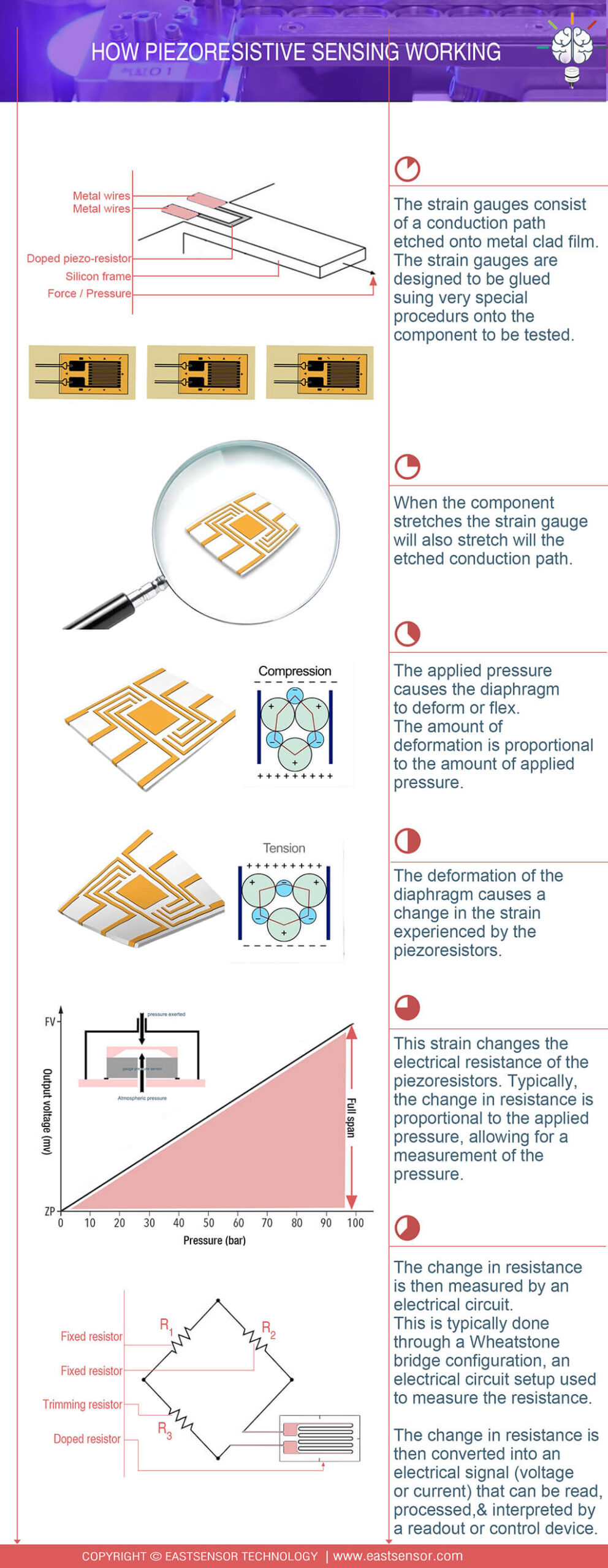
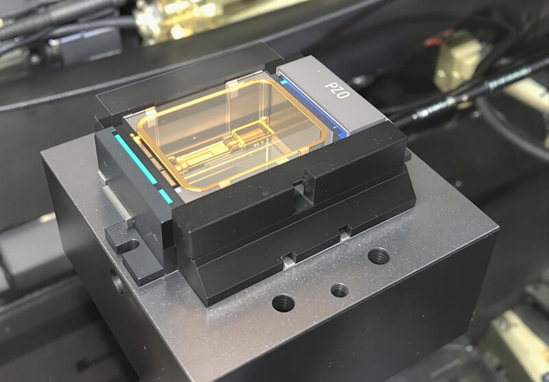
Piezoresistive (Most Common)
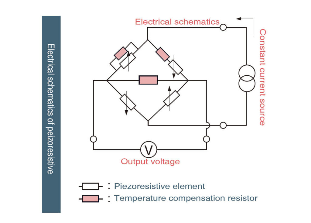
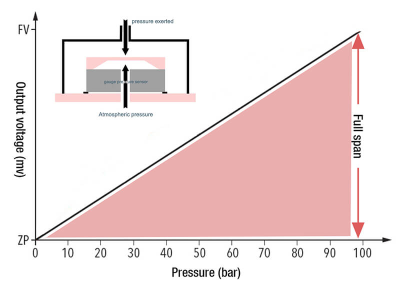
Piezoresistive sensors utilize materials whose electrical resistance changes when mechanically stressed. Pressure applied to the sensor deforms a diaphragm embedded with piezoresistive elements. This deformation alters the resistance, which is measured as a change in voltage across a circuit. This voltage change is then converted to a corresponding pressure reading. Their high output signal, robustness, and relative simplicity make them the most widely used pressure sensor type.
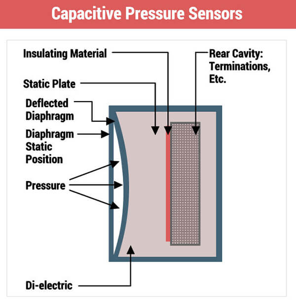
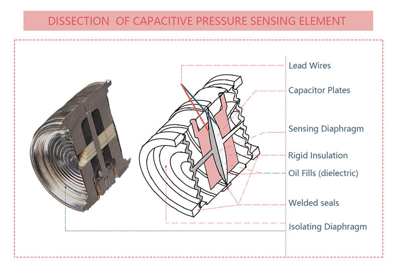
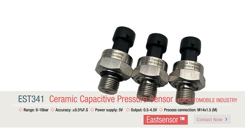
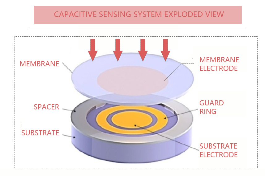
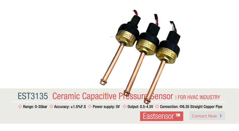
Capacitive
Capacitive sensors measure pressure based on changes in electrical capacitance. They consist of two conductive plates separated by a small gap, often with one plate being a flexible diaphragm. Applied pressure deflects the diaphragm, altering the distance between the plates and thus changing the capacitance. This capacitance change is detected electronically and converted into a pressure measurement. They offer good sensitivity, stability, and low power consumption, suitable for low-pressure ranges and harsh environments.
Piezoelectric
Piezoelectric sensors generate an electrical charge when subjected to physical force, utilizing the piezoelectric effect. Pressure applied to a piezoelectric crystal material creates a proportional charge across the crystal. This charge is measured and converted into a voltage signal representing the pressure. These sensors excel at measuring dynamic, rapidly changing pressures due to their high-frequency response and are often compact, but typically measure only changing pressure, not static pressure.
Optical
Optical sensors measure pressure by detecting changes in light properties. Pressure typically alters the position, shape, or refractive index of an optical element (like a diaphragm or fiber Bragg grating) within the sensor. This change modulates light intensity, phase, wavelength, or polarization traveling through the system. The modulated light signal is then analyzed to determine the applied pressure. They are highly immune to electromagnetic interference and suitable for remote sensing or hazardous environments.
Electromagnetic
Electromagnetic sensors measure pressure by detecting the movement of a ferromagnetic core within a coil. Pressure moves a diaphragm connected to the core. This displacement changes the inductance of the coil or the reluctance of a magnetic circuit. The resulting change in the coil’s electrical characteristics (inductance, impedance) is measured and converted to a pressure reading. They are robust and can handle high pressures but may be sensitive to external magnetic fields.
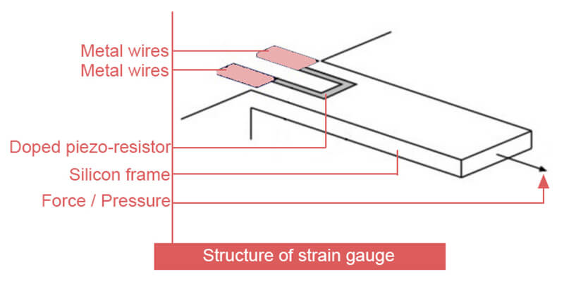
Strain Gauge
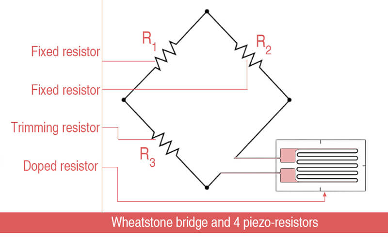
Strain gauge sensors rely on the principle that a material’s electrical resistance changes as it deforms under force. A spring element (like a diaphragm) deforms when pressure is applied. Strain gauges bonded to this element experience the same deformation, causing a proportional change in their electrical resistance. This resistance change, detected as a voltage shift in a Wheatstone bridge circuit, is calibrated to display the pressure. They are versatile, widely available, and excellent for long-term monitoring.
Resonant
Resonant sensors measure pressure by detecting shifts in the natural resonant frequency of a vibrating element. Pressure changes typically strain a diaphragm or beam designed to resonate at a specific frequency. This strain alters the element’s stiffness or mass, causing its resonant frequency to shift. The sensor electronics track this frequency change, which is directly correlated to the applied pressure. They offer very high accuracy, stability, and digital output capability.
Thermal
Thermal sensors measure pressure, especially gas pressure, by detecting changes in heat transfer properties. They contain a heated element. As gas pressure changes, the rate at which heat is conducted away from the element by the surrounding gas molecules also changes. This alters the element’s temperature and thus its electrical resistance (if a thermistor) or the power needed to maintain a constant temperature. This change is measured and correlated to pressure, common in vacuum and low-pressure applications.
8 Pressure Sensor Types: Features & Compassion
| Type | Key Features | Advantages | Disadvantages | Best For |
|---|---|---|---|---|
| Piezoresistive 🟢 MEMS/Cost/Size Efficient | Wheatstone bridge Wide range | ✅ Compact ✅ Low-cost ✅ DC static | ❌ Temp-sensitive ❌ Stability issues | Automotive Medical Industrial HVAC |
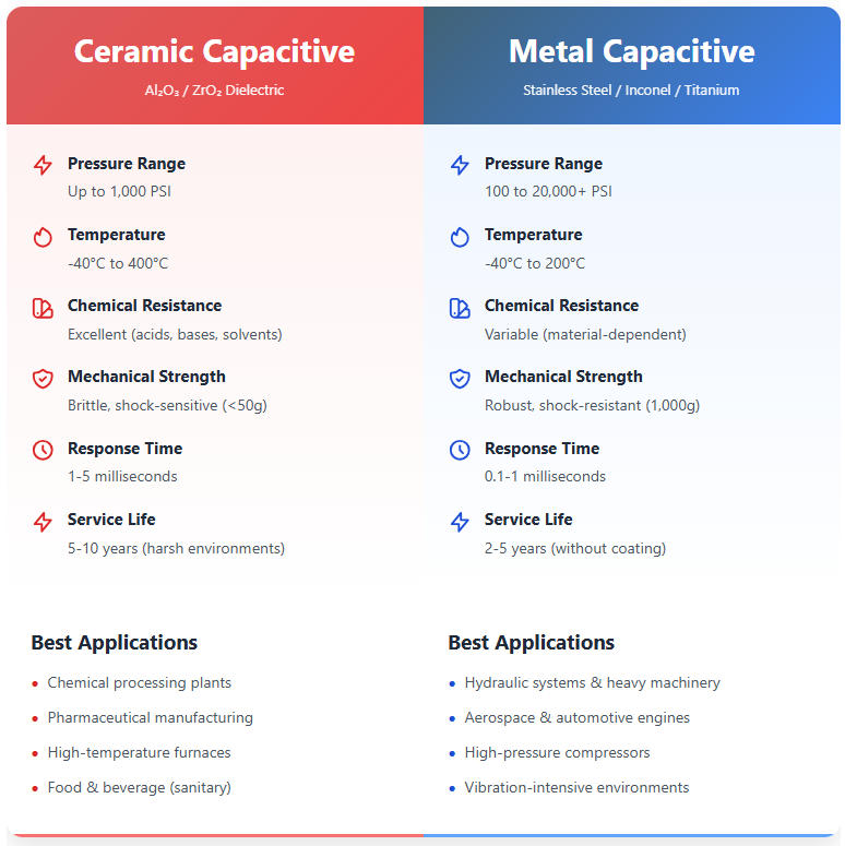
| Capacitive 🔵 Low-Pressure/Precision-focused | Δ Capacitance Diaphragm deflection | ✅ High sensitivity ✅ Low power ✅ Stable | ❌ Fragile ❌ EMI-prone ❌ Limited range | HVAC Ventilators Vacuum |
| Piezoelectric ⚡ Dynamic Pressure | Crystal charge (dQ = d·F) No DC power | ✅ kHz-MHz response ✅ Rugged | ❌ No static pressure ❌ Complex amp | Combustion Impact Acoustics |
| Optical 🌐 Extreme/Harsh-environment optimized | Light modulation Fiber/cavity | ✅ EMI-immune ✅ Harsh env ✅ Intrinsically safe | ❌ High cost ❌ Complex setup | MRI Downhole Aerospace |
| Electromagnetic ⛓️ Rugged/High durability | LVDT/wiper displacement | ✅ 20k+ psi tolerant ✅ Overload-proof | ❌ Large size ❌ Wear (pot.) | Hydraulics Valves |
| Strain Gauge 🎯 Precision/High accuracy | Bonded foil ΔR Metal diaphragm | ✅ <0.1% FS accuracy ✅ Stable | ❌ Temp-comp critical ❌ Hysteresis | Load Cells Test Labs |
| Resonant 💎 Ultra-Accurate | Frequency shift (Δf ∝ stress) | ✅ <0.01% FS accuracy ✅ Drift-free | ❌ Very high cost ❌ Shock-sensitive | Calibration Custody Flow |
| Thermal 🌡️ Vacuum/Low-Pressure | Gas heat transfer | ✅ No moving parts ✅ Cheap | ❌ Gas-specific ❌ Slow response | Vacuum Systems Freeze Dryers |
| Factor | Considerations |
|---|---|
| Pressure Range | Vacuum: Thermal/Capacitive Low: Capacitive Med/High: Piezoresistive/Strain Gauge/Electromagnetic |
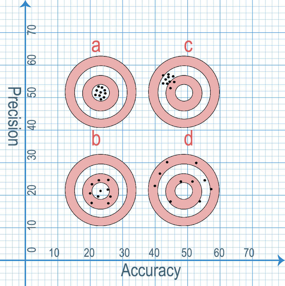
| Accuracy/Stability | Highest: Resonant/Strain Gauge High: Capacitive Good: Piezoresistive |
| Output Type | DC Static: Piezoresistive/Capacitive/Strain Gauge Dynamic: Piezoelectric Frequency: Resonant |
| Environment | Harsh/Chemical: Optical EMI: Optical High Temp: Optical/Piezoelectric |
| Cost/Size | Low Cost/Size: Piezoresistive MEMS High Cost: Resonant/Optical |
| Media Compatibility | Diaphragm isolation critical for corrosive media (applies to Piezoresistive/Capacitive/etc.) |
Key Pressure Sensor Applications
“The diverse Pressure Sensor Types available today unlocks numerous applications across your facility. This versatility means nearly any critical asset can benefit from pressure monitoring. Below we have listed some of the most common and impactful uses for reference.
Automotive systems
Pressure sensors are fundamental to vehicle safety and performance. They continuously monitor critical parameters like tire inflation pressure and engine oil pressure. Precise sensing ensures optimal engine operation, fuel efficiency, and alerts drivers to potential tire failures.
Medical devices
Patient care relies heavily on accurate pressure measurement. Sensors are vital components in non-invasive blood pressure monitors and respiratory equipment like ventilators and anesthesia machines. They deliver the precise pressure readings essential for patient diagnostics and life-sustaining therapies.
Industrial process control
Maintaining consistent production quality demands rigorous pressure monitoring. Sensors are embedded throughout manufacturing lines to regulate fluid flows, chemical reactions, and system pressures in real-time. This ensures processes operate within strict parameters for both product standards and operational safety.
Weather and environmental monitoring
Atmospheric pressure measurement remains crucial for weather forecasting. Beyond predicting storms, sensors are integral to environmental systems, tracking pollution levels, monitoring emissions control devices, and optimizing the performance of wind turbines and related management systems.
Aerospace and aviation
Flight safety is critically dependent on pressure sensing. Sensors monitor cabin pressure for passenger comfort and safety, measure altitude via static air pressure, and ensure the integrity of critical hydraulic and fuel systems operating under extreme flight conditions.
HVAC systems
Efficient building climate control hinges on pressure measurement. Sensors optimize airflow in ducts, monitor filter status to maintain air quality, regulate refrigerant pressures, and ensure balanced system operation – all contributing to significant energy conservation.
Hydraulic and pneumatic equipment
These high-power systems operate under significant stress, often reaching pressures of 3000 psi or more in hydraulics. Sensors constantly detect pressure anomalies, identify leaks, monitor pump health, and prevent catastrophic system failures by ensuring pressures stay within safe operating limits.
Oil and gas industry
Operations in this sector face extreme conditions, from pipeline pressures (often 200-1500 psi for gas transmission) to deep well drilling. Pressure sensors are essential for pipeline integrity monitoring, wellhead control, refining process efficiency, and ensuring safety compliance across all extraction and distribution phases.
Conclusion
Modern Pressure Sensor Types show the sophisticated successors to those early barometers, transforming the invisible push and pull of forces—whether gas, liquid, or solid—into precise, actionable data. They achieve this by exploiting how pressure induces minuscule physical changes in specialized materials: bending diaphragms, altering electrical resistance, generating charges, or shifting resonant frequencies.
This core principle—detecting physical deformation and converting it into an electrical signal—enables astonishing accuracy and reliability. The diversity of sensing mechanisms, from piezoresistive and capacitive to piezoelectric and optical, allows tailoring sensors to specific pressures, environments, and applications. Integrated with control systems like PLCs, these signals provide real-time insights, triggering automated responses to maintain safety and efficiency.
Crucially, pressure sensors have become ubiquitous, silent sentinels underpinning modern life. They ensure automotive safety and performance, enable life-saving medical diagnostics and treatments, guarantee industrial process control, deliver accurate weather forecasts, maintain aircraft cabin pressure, optimize HVAC efficiency, manage powerful hydraulic systems, and secure operations in the demanding oil and gas sector.
From historical curiosity to fundamental technology, pressure sensors have evolved into indispensable tools, continuously making the invisible forces shaping our world visible, measurable, and manageable.
FAQ
How have pressure sensors evolved?
From simple 1600s liquid-filled tubes (barometers) to today’s tiny silicon chips. Modern sensors detect microscopic material changes electronically, enabling extreme miniaturization, precision, speed, and integration into countless digital systems.
What is a pressure sensor?
It’s a device that detects the force (push) from gases, liquids, or solids and converts it into a measurable electrical signal. It makes invisible pressure visible as data we can use.
How does a pressure sensor work?
Pressure physically bends or deforms a tiny component (like a diaphragm) inside the sensor. This deformation changes an electrical property (resistance, capacitance, charge), creating a signal proportional to the pressure
What are the main types?
Common types are: Piezoresistive (resistance change, most popular), Capacitive (distance change), Piezoelectric (charge generation for fast changes), Strain Gauge (resistance via deformation), Optical (light change), Resonant (frequency shift), Thermal (heat transfer).
Why are piezoresistive sensors so common?
They offer a strong electrical signal, are robust, relatively simple, and work well across a wide range of pressures, making them versatile and cost-effective.
What's special about piezoelectric sensors?
They generate their own electrical charge when pressure changes quickly, making them ideal for measuring fast, dynamic pressures (like impacts), but not steady, static pressure.
Where are pressure sensors used?
Everywhere! Key uses: Car tires & engines, medical devices (BP monitors, ventilators), industrial processes, weather forecasting, aircraft systems, HVAC controls, hydraulic/pneumatic equipment, and oil/gas pipelines.
How do they improve safety and efficiency?
By providing real-time pressure data, they trigger automatic actions: prevent overpressure damage, detect leaks, optimize engine/process performance, ensure medical device accuracy, and maintain system balance (like HVAC).