Better Drilling with Better Data
Measures downhole pressure under harsh environment.
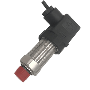
What is Drilling and Downhole Pressure Sensor?
A drilling and downhole pressure sensor is a specialized type of sensor designed to operate in the extremely harsh conditions found during oil and gas exploration and extraction processes. These can be quite deep below the Earth’s surface or subsea, in what’s known as the downhole environment.
Downhole pressure sensors are integral components of drilling and production operations in the oil & gas industry. Primarily, they serve two main functions:
- Real-Time Drilling
- Monitoring
Now let look at them one by one:
Real-Time Drilling-Related Readings:
Downhole pressure sensors are used to monitor real-time drilling conditions. The measurements provided by this sensor, including hydrostatic pressure, formation pressure, and overburden pressure, are essential to predictive modeling, drilling safety, and efficiency.
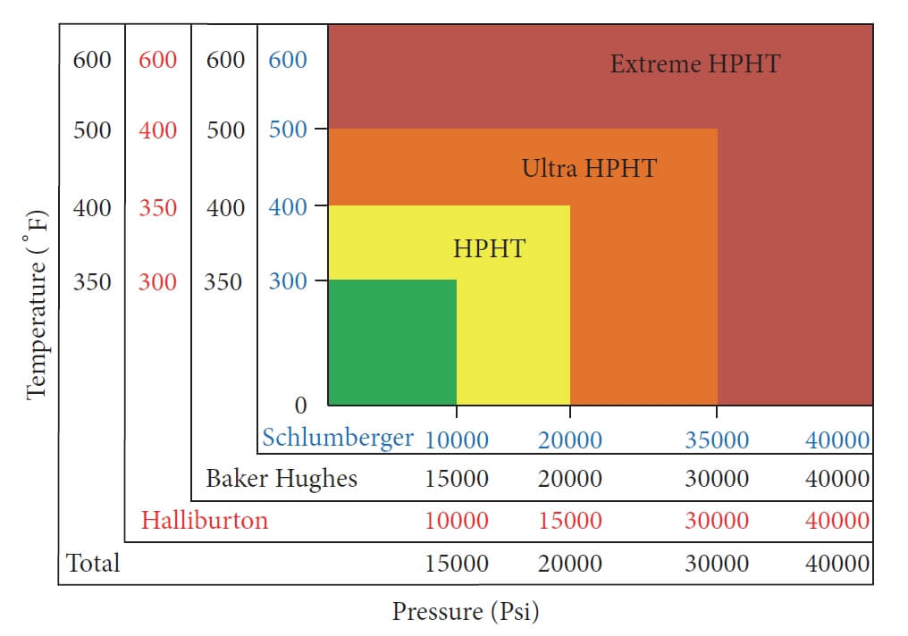
Technically, these sensors need to withstand and measure pressures up to 20,000 psi and temperatures up to 170°C or sometime 200 °C. Taking the ‘total vertical depth’ (TVD) into account, every incremental increase in TVD by 10 meters can approximately increase the hydrostatic pressure by 1 bar assuming an average fluid gradient.
Therefore, for deepwater drilling at depths of 10000 meters, a sensor must be precise enough to measure at least approximate pressures of 1000 bars.
Monitoring During Production:
Once a well is producing, downhole pressure sensors become a vital part of reservoir management. The reservoir’s estimated reserves, the rate of extraction, and the lifespan of the reservoir can all be calculated using the data from these pressure sensors.
As a practical guide, suppose a reservoir is at 10,000 psi initially, and data indicates a drop to 9,500 psi after extracting 100,000 barrels. We can extrapolate that when the pressure drops to 8,500 psi, we’d have extracted about 300,000 barrels using the statistical method of straight-line regression.
Designed to withstand harsh conditions (high temperature 170°C-200°C, high pressure 1000bar-1500bar, and corrosive environments), the data from downhole pressure sensors not only contributes to improving safety measures but also helps optimize production, ultimately leading to substantial cost savings and improved efficiencies in the oil and gas sector.
How to design a pressure sensor for Downhole and Drilling applications
Designing a pressure sensor for drilling and downhole applications involves a good understanding of the key operational demands, conditions, and limitations of such environments.
When it comes to the process of pressure sensor designing, you need to ensure the sensor’s design would be compact, rugged, and lightweight considering the harsh borehole environments.
Rugged Designing
Firstly, you must understand the requirement specifications like pressure range, temperature range, vibration limits, fluid compatibility, and response time. For instance, typical pressure sensors in downhole may need to operate between 0 to 22,000 psi and temperature up to 175 °C.
Such pressure sensors are always made using different technologies such as strain gauge, capacitive, piezoelectric, thin-film spluttering and resonant sensor technologies. The choice depends on factors like required accuracy, size, and cost. Often, piezoresistive sensors are preferred due to their high sensitivity and accuracy.
What is more, the materials must be chosen to endure high pressure, aggressive drilling fluids, high temperatures, and vibrations. Stainless steel can be used for its mechanical strength, but for higher thermal stability and corrosion resistance, materials like 17-4PH, Inconel or Hastelloy are preferred.
| SS304 | SS316 | 17-4PH | |
|---|---|---|---|
| Corrosion Resistance | Good | Better | Best |
| Strength | Lower | Medium | High |
| Cost | Low | Medium | High |
| Weldability | High | Medium | Low |
| Formability | High | Medium | Low |
| Typical Use | Most applications | Marine and chemical environments | Severe service conditions |
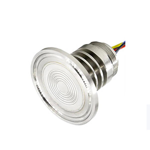
Sensing Mechanism
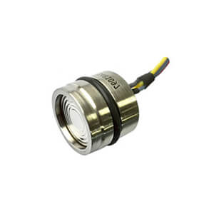
Thin-film sensors serve as an excellent choice for downhole applications for varied reasons. They’re made by vacuum depositing a layer of sensitive material (like platinum) on a substrate, forming a set of resistors within the circuit.
In usual, there are mainly 2 relevant areas (Piezoresistive and Capacitive) in which thin-film sensors are critical, however mostly we are talking about the piezoresistive one.
In thin-film spluttering piezoresistive sensors, a pressure-inducing mechanical deformation results in a change in the electrical resistance of a thin film layer. The pressure-sensitive diaphragm, the substrate where the thin film is deposited, deforms under the applied pressure, and as a result, the resistance in the thin film changes.
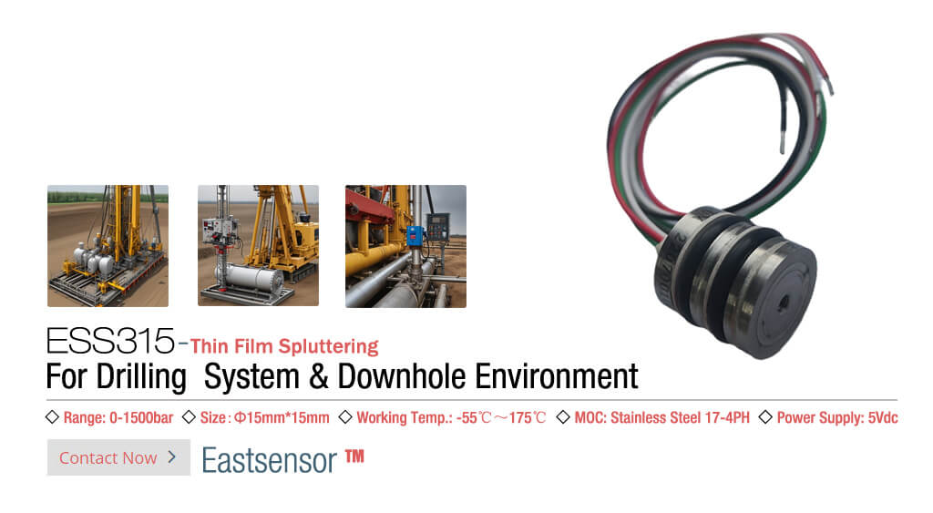
Click to check out: ESS315 Thin-Film Spluttering Pressure Sensor
Usually, the thin film is organized into a Wheatstone bridge circuit configuration. The piezoresistive thin-film elements change their resistance asymmetrically when pressure is applied, causing a shift in the bridge’s output voltage that can be linked back to the applied pressure.
In this scenario, the thin films prove to be largely immune to the effects of temperature and can have excellent chemical resistance. It is also the pertinent aspect when considering downhole applications, where pressure sensors can be exposed to extreme temperatures and corrosive materials.
Signal conditioning
Designing downhole pressure sensors indeed requires a thorough understanding of Signal Conditioning, which forms a crucial aspect of attaining reliable sensor outputs. As for post-measurement, the electrical signal undergoes amplification and conversion, usually within the downhole tool, by conditioning circuits.
Typically, a Wheatstone bridge arrangement is used for amplification of the signal and at least the amplification and filtering are the top 2 aspects that you need to know:
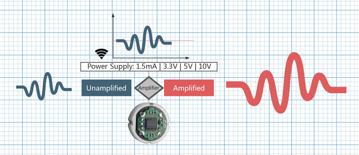
Amplification: As downhole pressure sensors usually operate in a high-pressure environment the sensors will generate a relatively small output voltage. This needs to be amplified so that we can record or transmit it.
For example, strain gauges arranged in a Wheatstone bridge often output a differential signal on the order of a few millivolts. Amplifiers, in this case, bring the voltage to a level suitable for the rest of the system, which might be a few volts.
Most commonly a type of amplifier known as an instrumentation amplifier is used because of its superior common-mode rejection, low DC offset, and gain accuracy.
Filtering: Signal filtering is another significant aspect of signal conditioning. Considering that downhole environments are full of electrical noise caused by a host of factors such as machinery, power lines, and natural radioactivity, it is crucial to filter out these unwanted signals.
Filters can be low pass, high pass, band pass and band stop. Low pass filters, for example, are often used to eliminate the high-frequency noise. For a simple RC filter, the cut-off frequency is given by fc = 1 / (2 * pi * R * C), where R is the resistance, and C is the capacitance.
These two signal conditioning methods, when used correctly, can drastically improve the reliability and accuracy of downhole pressure sensors. The raw signal from the sensor is both amplified and filtered, ensuring that the pressure readings are accurate and free from any electrical noise interference, providing very clean and usable data for evaluation.
The design of downhole pressure sensors is an intricate process, needing a comprehensive understanding of both mechanical and electrical engineering principles, but the ones above are the primary considerations.
In any circumstance, remember, safety and reliability in the harsh downhole environment should always be the top priority.
Take an example:
Above may we talk about more details of drilling and downhole pressure sensor, now let take an east understanding example as following to help you get a quick comprehension.
Conceptualizing the differences between a normal pressure sensor and a pressure sensor designed for drilling and downhole applications can be likened to comparing a standard car and a submarine.
A standard car (like a “normal” pressure sensor) is designed to operate in relatively benign conditions. It can handle a range of environments like city roads or countryside lanes (equivalent to various industrial settings) and needs to cope with changes in temperature, but nothing too extreme. Similarly, a standard pressure sensor can typically handle pressures up to about 6000 PSI (around 400 Bar) and temperatures between -20 to 85 °C, which is suitable for many industrial settings.
On the other hand, a submarine (like a pressure sensor for drilling & downhole applications) is designed for the harsh, deep-sea environment. It has to withstand enormous pressures of the deep sea, corrosive saltwater, and significant temperature changes. Similarly, a pressure sensor for downhole applications has to endure pressures up to 20,000 PSI (around 1400 Bar) and persist in extreme temperatures often up to 200 °C.

So, in a nutshell, while both “normal” pressure sensors and those designed for drilling and downhole applications serve the same basic function—measuring pressure—the latter is created to survive and function accurately in much more extreme conditions.