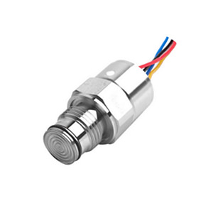
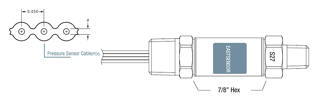
Cable for Pressure Sensor
Pressure Sensor Cable Maintenance
Continue: Pressure Sensor Cable part 1/2
This section will discuss inspection and cleaning procedures, identifying and repairing damaged cables, and best practices for replacement and disposal.
First, let’s review the inspection and cleaning procedures for pressure sensor cables:
- Regular inspections:
Perform routine pressure sensor cables and connectors inspections to identify any signs of wear, corrosion, or damage. A regular inspection schedule should be established based on the criticality of the application and environmental conditions.
- Cleaning:
In cases where contamination, dust, or grime is present, clean the cable and connector surfaces with a soft brush and a mild cleaning agent or isopropyl alcohol. Ensure the cleaning agents used are compatible with the cable and connector materials.
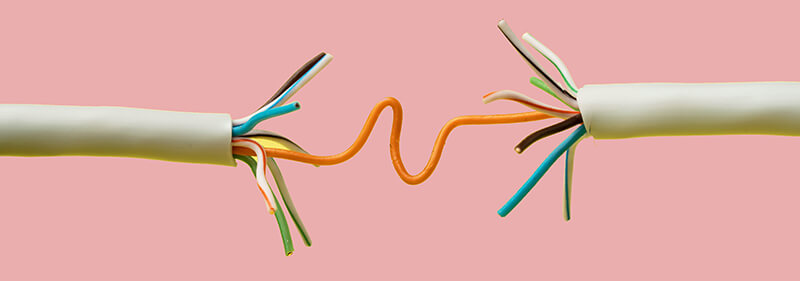
Next, we will discuss the process of identifying and repairing damaged cables:
- Visual inspection:
Check for external damage, such as cuts, nicks, or abrasions on the cable insulation. Additionally, inspect connectors for signs of corrosion or loose connections.
- Continuity testing:
Use a multimeter to perform continuity tests on the cable conductors, ensuring that there are no breaks or short circuits.
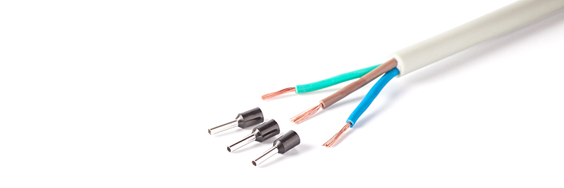
- Repair or replacement:
If damage is found, assess whether it is possible to repair the cable, such as by insulating exposed conductors with heat shrink tubing, or if the entire cable needs to be replaced.
Lastly, let’s review the best practices for cable replacement and disposal:
- Follow manufacturer guidelines:
When replacing damaged cables or connectors, adhere to the manufacturer’s recommendations regarding suitable components and installation procedures.
- Safe disposal:
Ensure proper disposal of damaged cables and connectors according to local environmental and waste management regulations.
Performance Metrics and Testing
This section will delve deep into the essential performance metrics and testing processes critical to selecting the right pressure sensor cable for your applications. We’ll investigate three crucial tests: resistance and capacitance measurements, insulation resistance tests, and checks for electrical continuity.
Measuring the resistance and capacitance of pressure sensor cables is vital for assessing the signal loss, noise immunity, and overall cable performance. Understanding these parameters will help you choose a cable that maximizes pressure measurement accuracy and responsiveness.
- Resistance: By measuring the resistance of the conductors and shields within the cable, we can assess its electrical performance, signal attenuation, and heat dissipation. The cable’s resistance should be low, typically in the range of 10 – 100 ohms per kilometer (ohm/km). A lower resistance value ensures minimal signal distortion and minimizes the influence of external factors, such as temperature variations.
—————————————————————–
- Capacitance: Capacitance is the ability of the pressure sensor cable to store electrical energy, affecting signal transmission and noise immunity. Lower capacitance values, typically between 50 – 100 picofarads per meter (pF/m), lead to better signal transmission and reduced susceptibility to electromagnetic interference (EMI). Consequently, selecting a cable with a suitable capacitance value is essential to optimize pressure measurement accuracy and stability.
- Insulation Resistance Tests
Insulation resistance tests evaluate the effectiveness of a cable’s insulation in preventing electrical leakage and ensuring signal isolation. These tests help ensure that pressure sensor cables can operate reliably and maintain accuracy in demanding environments exposed to moisture, contaminants, or extreme temperatures.
Insulation resistance values should be high, typically in the order of megaohms (MΩ) to gigaohms (GΩ). The higher the insulation resistance, the less susceptible the cable is to electrical leakage and external interference, resulting in improved signal integrity and reliability.
- Testing for Electrical Continuity
Electrical continuity tests check for open or short circuits within the pressure sensor cable that might compromise signal transmission or create potential hazards. Ensuring electrical continuity throughout the cable ensures accurate pressure readings and reduces the risk of equipment failure.
Common Causes of Pressure Sensor Cable Failures
Now, we will explore the various factors that can lead to cable failure, which in turn impacts the accuracy and reliability of pressure measurement. Understanding these factors will help you effectively prevent and troubleshoot issues in your pressure-sensing applications.
Let us focus on physical damage due to improper installation, environmental exposure, and manufacturing defects or quality issues.
- Physical Damage
Physical Damage due to Improper Installation Incorrect handling or installation of pressure sensor cables can result in physical damage that compromises their performance, leading to inaccurate or unreliable measurements. Some examples of damage caused by improper installation include:
- Kinks or severe bends in the cable, which can break internal conductors and affect signal transmission.
- Over-tightening cable glands, strain relief devices or connectors may result in crushed insulation and electrical short circuits.
- Embedded stress on the cable due to stretching or pulling, causing micro-cracks in the insulation and weakening the overall cable structure.
- Environmental Exposure
Environmental Exposure Pressure sensor cables can be subjected to various environmental stresses that may cause cable failure over time. These include:
- Temperature extremes: Prolonged exposure to high or low temperatures can cause the insulation and jacket materials to crack or degrade, compromising the cable’s electrical integrity.
- Moisture ingress: Penetration of water or moisture into the cable can lead to insulation breakdown, corrosion, and electrical short circuits.
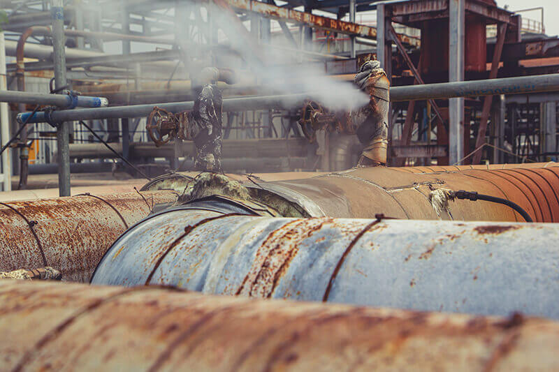
- Chemical exposure: Contact with harsh chemicals, fuels, or solvents may degrade cable materials, resulting in structural damage or reduced performance.
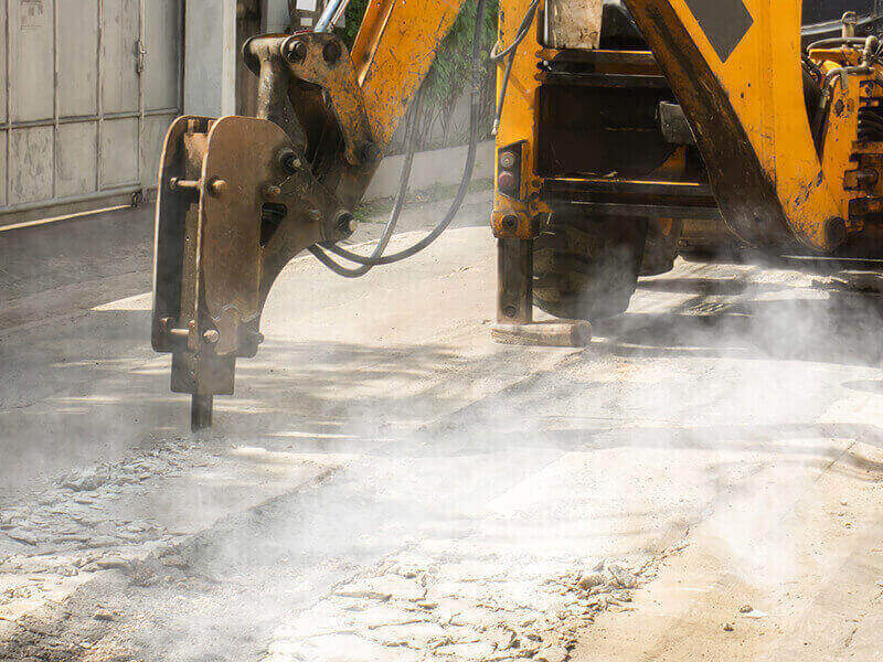
- Mechanical stress: Exposure to abrasion, vibration, or impact damages the cable and may result in signal loss or complete cable failure.
- Manufacturing Defects
Manufacturing Defects or Quality Issues Defects or quality issues during the manufacturing process of pressure sensor cables can result in reduced performance or premature failure. Some examples of manufacturing defects include:
- Inadequate or inconsistent insulation, leaving gaps or thin areas vulnerable to electrical leakage.
- Incorrect soldering or termination of cable connectors, leading to poor electrical contact or mechanically weak connections.
- Dimensional inaccuracies cause improper fitment of the cable within the sensor assembly, resulting in uneven stress on the cable when installed.
Troubleshooting Pressure Sensor Cable Issues
In this part, we will discuss identifying the root cause of performance issues, the available diagnostic tools and techniques, and methods for repairing or replacing faulty cables. Diagnosing and addressing pressure sensor cable problems is critical to maintaining accurate and reliable pressure measurements for your systems.
- Identifying the Root Cause of Performance Issues
To effectively troubleshoot pressure sensor cable issues, it is essential first to identify the underlying causes of the problems. As discussed in the previous sections, typical reasons for cable failure include physical damage due to improper installation, environmental exposure, and manufacturing defects or quality issues.
- Perform a visual inspection of the cable to identify any signs of wear or damage such as kinks, abrasions, or insulation breakdown.
- Consider the environmental conditions that the cable is exposed to, which could impact its performance, such as temperature extremes, moisture, or harsh chemicals.
- Check for any potential manufacturing defects like poor soldering, inadequate insulation, or dimensional inaccuracies in the connectors.
- Diagnostic Tools and Techniques
Several diagnostic tools and techniques exist to help identify pressure sensor cable issues, including:
- Multimeters: Use a multimeter to measure the cable’s resistance, capacitance, and insulation resistance to determine its electrical performance.
- Voltage drop test: Perform a voltage drop test to measure the amount of voltage lost due to resistance in the cable’s conductors and connectors.
- Time Domain Reflectometry (TDR): This technique uses a specialized TDR instrument that sends a signal down the cable and analyzes the reflected signal to identify issues like discontinuities or impedance mismatches.
- Repairing or Replacing Faulty Cables
Once the root cause is identified, you can decide whether to repair or replace the faulty pressure sensor cable:
- Repair: Minor issues such as loose connectors or small abrasions on the cable jacket can be resolved by re-terminating the connectors or applying suitable patch material.
- Replace: If the cable exhibits significant damage, degradation, or manufacturing defects, it may be necessary to replace it with a new, high-quality pressure sensor cable suitable for the application.
Advanced Pressure Sensor Cable Technologies
Let us explore the latest developments in materials, miniaturization, and smart cables with integrated electronics. These advancements are shaping the future of pressure sensing applications, enabling more robust, versatile, and high-performing solutions.
- Improved Materials for Harsh Conditions
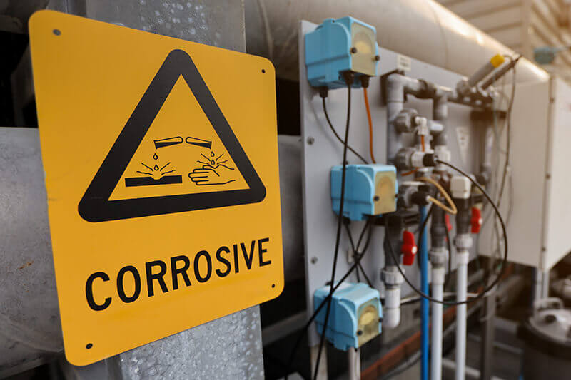
Emerging materials are revolutionizing pressure sensor cables’ performance in extreme conditions such as high temperatures, corrosive environments, and heavy-duty applications.
- High-temperature materials: Advanced polymers like polyimide (Kapton), polytetrafluoroethylene (PTFE, Teflon), and fluoroelastomers (Viton) can withstand temperatures exceeding 200°C, ensuring durability and longevity in harsh thermal conditions.
- Corrosion-resistant materials: Enhanced jacket and insulation materials, such as ethylene propylene diene monomer (EPDM) rubber, provide excellent resistance against acids, alkalis, oils, and other aggressive chemicals, safeguarding cable integrity in corrosive environments.
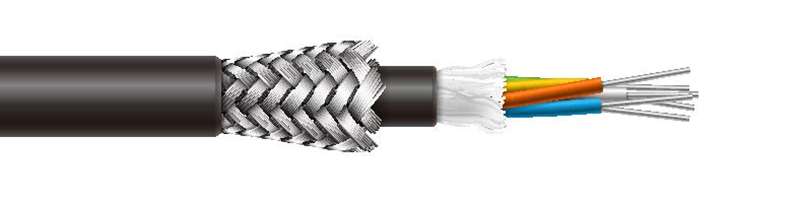
- Ruggedized designs: Reinforced braids or armor layers can protect sensor cables from mechanical stresses like abrasion, vibration, impact, and crushing forces, ensuring reliable performance in heavy-duty applications.
- Miniaturization and Increased Flexibility
Advancements in cable manufacturing technologies enable the production of miniaturized and highly flexible pressure sensor cables, opening up new possibilities in tight spaces and complex installations.
- Thinner insulation and jacket materials: Advanced polymers and manufacturing techniques allow for thinner insulation and jackets without compromising performance, resulting in a smaller overall cable diameter.
- Enhanced conductor design: The use of finer conductor strands and optimized strand lay lengths can increase cable flexibility, allowing for easier routing, bending, and installation in tight or space-constrained applications.
- Smart Cables with Integrated Electronics
Innovations in electronics and sensor technology have led to the development of smart pressure sensor cables that bring intelligence and functionality closer to the measuring point.
- Integrated signal conditioning: Smart cables with built-in signal conditioning circuitry can amplify and filter the pressure sensor’s output signal, ensuring accurate and noise-free transmission.
- Digital communication: The integration of digital communication protocols like I²C, SPI, or RS-485 enables real-time data transfer, improved noise immunity, and simplified wiring between the pressure sensor and the control systems.
- Advanced diagnostics: Embedded electronics within smart cables can monitor cable health and performance, detecting potential issues like physical damage, insulation degradation, or transient electrical events for proactive maintenance and troubleshooting.
Case Studies: Pressure Sensor Cable Applications
This section will examine case studies showcasing how these cables are employed in industrial automation, marine and offshore applications, and automotive and aerospace sectors.
By understanding each application’s unique challenges and demands, we can better appreciate the importance of selecting the right pressure sensor cable for accurate and reliable pressure measurement.
-
Industrial Automation and Process Control
Pressure sensor cables play a vital role in industrial automation and process control, monitoring vital parameters in various systems for process optimization, safety, and efficiency.
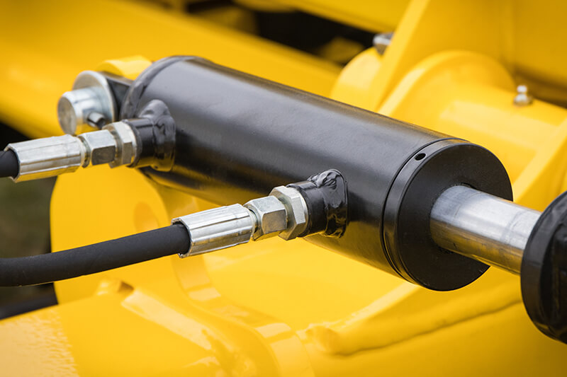
- Pumps and compressors: Pressure sensor cables connect to transducers monitoring hydraulic or pneumatic pressure in pump and compressor systems, ensuring operational efficiency and maintaining safe operating pressures.
- HVAC systems: In heating, ventilation, and air conditioning systems, pressure sensor cables connect to sensors measuring duct pressure, airflow, and refrigerant pressure to enhance energy efficiency, system reliability, and user comfort.
- Chemical processing plants: Pressure sensor cables in chemical plants may require corrosion-resistant materials and advanced shielding to withstand exposure to harsh chemicals and potential electromagnetic interference (EMI) from high voltage equipment.
-
Marine and Offshore Applications
In marine and offshore environments, pressure sensor cables must withstand demanding and harsh conditions such as exposure to seawater, temperature changes, and moisture ingress.
- Subsea pressure measurement: Pressure sensor cables are used to connect deep-sea pressure sensors to surface monitoring systems in submersible vehicles, logging pressure conditions at various depths.
- Dynamic positioning systems: In offshore platforms or vessels, cables connect pressure sensors that monitor thruster performance and hydrodynamic forces, ensuring accurate and stable dynamic positioning.
- Marine fuel systems: Pressure sensor cables are employed in fuel system monitoring, detecting changes in fuel line pressure to ensure smooth engine operation, fuel efficiency, and compliance with environmental regulations.
-
Automotive and Aerospace Applications
Pressure sensor cables are crucial to automotive and aerospace applications, where high-performance, lightweight, and reliable cables for pressure measurement are essential.
- Engine monitoring systems: Pressure sensor cables connect to sensors that monitor oil, coolant, and fuel pressure in engines, enhancing performance and identifying potential issues for more efficient operation and reduced maintenance costs.
- Tire pressure monitoring systems (TPMS): In vehicles equipped with TPMS, pressure sensor cables communicate tire pressure data to the vehicle’s onboard monitoring systems, ensuring driver safety and optimizing fuel efficiency.
- Aircraft hydraulic systems: Pressure sensor cables are used to transmit information from sensors in aircraft hydraulic systems that control landing gear, brakes, and flight control surfaces, enabling safe and efficient operation during critical flight phases.
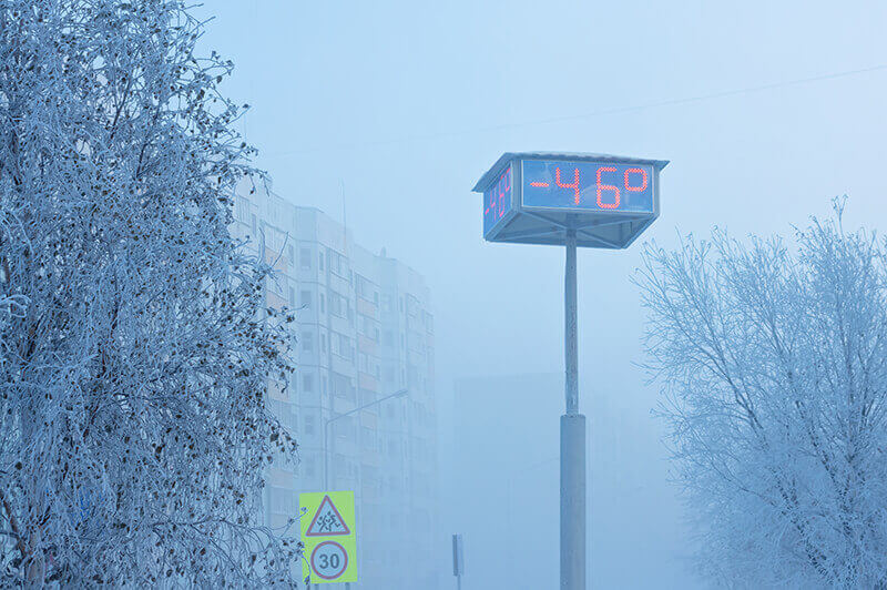
4. Working under code and extreme code conditions
Now let’s discuss the challenges pressure sensor cables face in cold environments. Temperature fluctuations can cause materials to contract, leading to insulation cracking, brittleness, or even breakage in extreme cases. Moreover, the electrical properties of the conductors may alter, resulting in inaccurate signal transmission and a higher risk of electrical noise interference.
Let’s dive into the essential factors to consider when choosing the right pressure sensor cable for cold and extreme cold conditions:
Insulation Material: Selecting a cable with insulation specifically designed for low-temperature applications is crucial. Thermoplastic materials, such as polyurethane (PUR) and fluoropolymers like polytetrafluoroethylene (PTFE), offer excellent cold resistance. For instance, PUR can retain its flexibility and toughness at temperatures as low as -40°C, while PTFE can perform well even at -60°C.
Conductor Material: The choice of conductor material is equally important, as it affects the cable’s electrical properties. In cold conditions, it is preferable to use materials with a low temperature coefficient of resistance, such as oxygen-free copper (OFC). This ensures minimal resistance changes and maintains the integrity of the pressure sensor signals.
Cable Shielding: Shielding plays a pivotal role in reducing noise interference and maintaining signal integrity. When it comes to cold environments, consider cables with foil or braided shielding that can withstand temperature-induced stress without compromising performance. For optimal results, opt for cables with a combination of both foil and braided shielding.
Cable Jacket: The cable’s outer jacket should be durable and cold-resistant to protect the internal components. Look for jackets made from thermoplastic elastomers (TPE), thermoplastic vulcanizate (TPV), or silicone rubber. These materials are known for their flexibility, toughness, and resistance to cracking in low temperatures.
Cable Flexibility: In cold environments, cables can become rigid, making them susceptible to damage during installation or movement. To overcome this, select a cable with a high strand count and fine-strand conductors, which provide greater flexibility and reduce the risk of breakage.
By considering factors such as insulation material, conductor material, shielding, cable jacket, and cable flexibility, you can make an informed decision that will meet the demands of your specific application. Stay informed, choose wisely, and optimize your pressure sensor system to tackle cold weather challenges.
Continue: Pressure Sensor Cable part 1/2