Introduction
What is Pressure Sensor Offset? Imagine setting your bathroom scale to zero, only to find it reads 5 pounds before you even step on it. This is essentially what happens with pressure sensor offset—a persistent error that affects every measurement your sensor takes.
In industrial applications, medical devices, and precision instruments, even small offset errors can lead to costly mistakes, safety issues, or product failures.
Throughout this comprehensive guide, you’ll discover what causes offset drift, how to accurately detect it in your systems, and most importantly, proven techniques to correct and prevent these errors. Whether you’re troubleshooting an existing installation or designing a new measurement system, understanding pressure sensor offset is crucial for maintaining accuracy and reliability.
What is Pressure Sensor Offset?
Understanding the Fundamentals
At its core, pressure sensor offset is the non-zero output reading that occurs when zero pressure is applied to the sensor, it is kind of adjustable errors.

To put it simply, it’s like a ruler that doesn’t start at zero—every measurement will be off by the same amount. This baseline shift affects all subsequent readings equally, whether you’re measuring low pressures or high pressures.
Technically speaking, offset is measured in the same units as your sensor output, such as millivolts (mV), milliamps (mA), or digital counts in ADC systems.
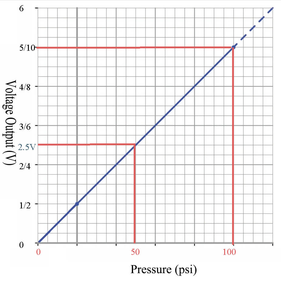
For instance, a pressure sensor with a 0-10V output range might show 0.05V when exposed to atmospheric pressure in a zero-reference measurement, indicating a 50mV offset error.
Distinguishing Offset from Other Errors
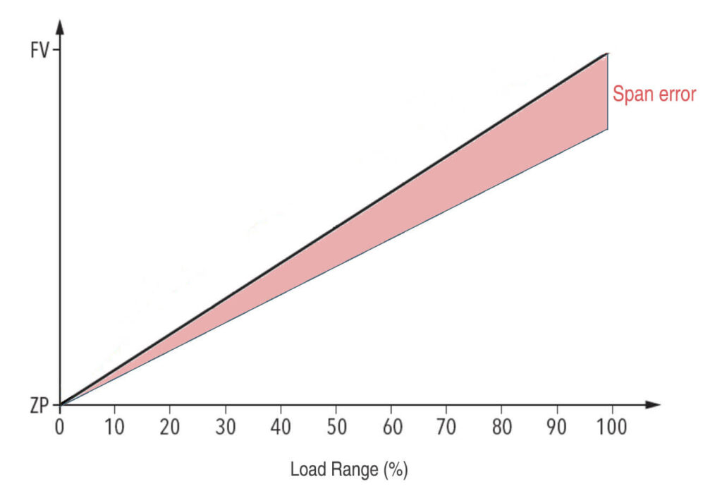
However, it’s essential to differentiate offset from other common sensor errors. Unlike span error, which affects the slope or gain of the sensor’s response curve, offset specifically impacts only the zero point.
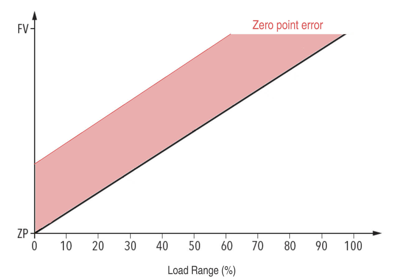
Meanwhile, span error causes the sensor to read incorrectly at full scale while potentially being accurate at zero. Furthermore, linearity errors create inconsistencies across the measurement range, whereas offset shifts the entire curve uniformly up or down.
Consequently, when you visualize offset on a calibration curve, you’ll see the measured response line running parallel to the ideal response line but displaced vertically. The slope remains correct, but the y-intercept has shifted. This characteristic makes offset errors relatively straightforward to correct compared to non-linear errors that vary across the measurement range.

Root Causes of Pressure Sensor Offset
Temperature Drift
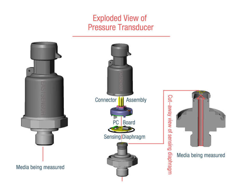
Perhaps the most common culprit behind pressure sensor offset is temperature variation. As ambient temperature changes, the physical properties of the sensor’s diaphragm, strain gauges, or capacitive elements shift accordingly. This thermal effect can cause the zero-point reading to drift significantly, even when the actual pressure remains constant.
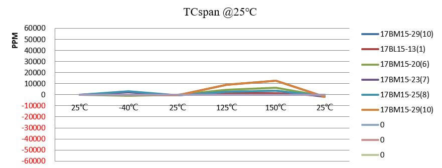
For instance, a piezoresistive pressure sensor might exhibit offset drift of 0.02% per degree Celsius. Therefore, a 20°C temperature swing could introduce a 0.4% offset error—substantial enough to compromise measurements in precision applications. Moreover, rapid temperature changes tend to cause larger temporary offsets than gradual shifts, as thermal equilibrium takes time to establish throughout the sensor structure.
Mechanical Stress and Mounting Issues
Beyond temperature, mechanical factors play a critical role in offset stability. When sensors are improperly mounted or subjected to excessive torque during installation, residual stress builds up in the sensing element. This stress subsequently creates a permanent or semi-permanent offset that persists even after the installation forces are removed.
Similarly, vibration and mechanical shock can gradually alter the sensor’s zero point over time. In harsh industrial environments where equipment experiences constant vibration, this cumulative effect becomes particularly problematic.
Furthermore, package stress from thermal expansion mismatches between the sensor die and its housing can introduce additional offset components that vary with temperature cycling.
Aging and Long-Term Drift
Even under ideal conditions, pressure sensors naturally experience offset drift as they age. This phenomenon occurs because the materials in the sensing element undergo subtle structural changes over months and years of operation. Consequently, sensors that were perfectly calibrated when new may develop noticeable offsets after extended service.
Research shows that offset drift typically follows a logarithmic pattern, with the most significant changes occurring during the first few months of operation. After this initial “break-in” period, the drift rate generally decreases but never completely stops. Therefore, establishing periodic recalibration schedules becomes essential for maintaining long-term accuracy.
Environmental Contamination
Additionally, environmental factors can introduce offset errors through various mechanisms. Moisture ingress into sensor ports can alter the electrical characteristics of sensing elements, particularly in capacitive pressure sensors. Likewise, chemical contamination from process fluids or atmospheric pollutants may attack sensor materials, causing permanent changes to the zero-point reference.
In one documented case, a manufacturing facility experienced mysterious offset drift in their pressure monitoring system. Investigation revealed that airborne silicone compounds from nearby molding operations were depositing on sensor diaphragms, creating a thin film that altered their mechanical response. Once identified, implementing protective barriers eliminated the problem entirely.
Power Supply Variations
On the electrical side, unstable power supplies frequently contribute to apparent offset errors. Although these aren’t true sensor offsets, power supply fluctuations affect the sensor’s output in ways that appear identical to offset drift. Specifically, voltage regulators with poor line regulation can cause the sensor’s reference voltage to shift, thereby changing all output readings proportionally.
This issue becomes especially prevalent in battery-powered applications where supply voltage gradually decreases as batteries discharge. Unless properly compensated, this voltage sag translates directly into apparent offset drift that worsens throughout the battery’s lifecycle.
Manufacturing Tolerances
Finally, inherent manufacturing variations ensure that no two sensors leave the factory with identical offset characteristics. Even sensors from the same production batch exhibit offset spread due to microscopic differences in materials, dimensions, and assembly processes. While manufacturers typically calibrate and trim sensors before shipment, some residual offset always remains within the specified tolerance band.
How to Detect Pressure Sensor Offset
Zero-Pressure Testing Methods
The most straightforward approach to detecting offset involves exposing the sensor to a known zero-pressure condition and observing its output.
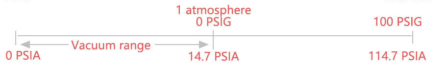
For absolute pressure sensors, this means creating a vacuum reference close to 0 psia. In contrast, gauge pressure sensors should be vented to atmospheric pressure, which serves as their zero-reference point.
To perform this test accurately, first ensure the sensor has reached thermal equilibrium with its environment. Temperature gradients can create temporary offset-like readings that disappear once stabilization occurs. Next, remove any process connections and vent the sensor port to atmosphere (for gauge sensors) or connect to a calibrated vacuum source (for absolute sensors). Then, record the output reading over several minutes to account for any short-term fluctuations.
Comparison with Reference Standards
Alternatively, when zero-pressure testing isn’t practical, comparing your sensor against a calibrated reference standard provides reliable offset detection.
This method works particularly well for sensors installed in systems where disconnection is difficult or undesirable. Essentially, you’re applying the same known pressure to both your sensor and a traceable reference instrument simultaneously.
For optimal results, select a reference standard with accuracy at least four times better than your sensor’s specification—this 4:1 ratio ensures the reference uncertainty doesn’t significantly contaminate your offset measurement.
Statistical Analysis of Baseline Readings
Beyond single-point checks, trending baseline readings over time reveals gradual offset drift before it becomes problematic. This preventive approach involves regularly recording sensor outputs under consistent conditions and analyzing the data for systematic shifts. Specifically, plot your zero-point readings versus time and look for trends that indicate developing offset issues.
Signs and Symptoms
In practice, several telltale signs suggest offset problems even without formal testing.
First, consistent bias in one direction across all measurements typically indicates offset rather than random errors. Second, if your process control system requires unusual setpoint adjustments to maintain target values, underlying offset drift may be the culprit.
Additionally, disagreement between redundant sensors measuring the same pressure often points to offset differences between instruments. When one sensor consistently reads higher or lower than its peers under identical conditions, offset error is the likely explanation.
Similarly, failing routine calibration checks at the low end of the range while passing at mid-scale strongly suggests offset issues.
Required Tools and Equipment
Detecting offset accurately requires appropriate tools depending on your sensor type and application.
At minimum, you’ll need a precision digital multimeter or data acquisition system capable of resolving your sensor’s output to at least 0.1% of its range.
For current-loop sensors outputting 4-20mA, a quality ammeter with 0.01mA resolution is essential.
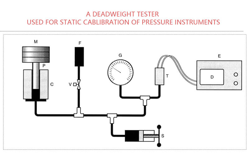
Moreover, reference pressure sources are indispensable for quantitative offset measurement. Depending on your pressure range, this might include a deadweight tester, precision pressure calibrator, or simply atmospheric pressure for gauge sensors. Temperature monitoring equipment also helps, since documenting ambient temperature during offset measurements enables temperature compensation calculations.
Step-by-Step Detection Procedure
To systematically detect offset, follow this proven procedure.
- Initially, allow the sensor to stabilize thermally for at least 30 minutes in its operating environment.
- Meanwhile, prepare your measurement equipment and reference pressure source.
- Subsequently, apply the zero-pressure reference condition and wait an additional 5-10 minutes for pressure equilibrium.
Then, record at least 10 consecutive readings at 30-second intervals to average out noise and capture any drift during the measurement period. After that, calculate the mean of these readings—this represents your measured offset.
Finally, compare this value against the sensor’s specified offset tolerance and your application’s accuracy requirements to determine if correction is necessary.
Key Highlights of Pressure Sensor Offset
| Topic | Key info |
|---|---|
| Definition | Offset = sensor reads non-zero at true zero |
| Also called | Zero offset, zero-point error |
| Main impact | Biases all readings; triggers wrong control/alarms |
| Not the same as | Span error (slope), nonlinearity, hysteresis |
| Common where | Low-pressure ranges, temperature swings, gauge sensors |
FAQ
What's the difference between pressure sensor offset and drift?
Offset is the error at zero pressure right now—like a scale reading 2 pounds with nothing on it. Drift is how that offset changes over time. A sensor can have perfect zero today but drift significantly after six months of use.
Can I just ignore small offset errors?
Only if your application has loose accuracy requirements.
Small offsets become critical when measuring low pressures (where they’re a large percentage of reading), in control loops (causing unnecessary corrections), or when combined with other errors that multiply the total inaccuracy.
How often should I check for offset?
Monthly for the first six months after installation, then quarterly once stable. Increase frequency after maintenance, temperature extremes, or if you see unexplained process shifts. Non-critical systems can often use annual checks.
Will recalibrating fix offset permanently?
No.
Recalibration corrects current offset but doesn’t stop future drift from temperature, aging, or mechanical stress. Regular recalibration schedules are necessary, not one-time fixes.
Do digital pressure sensors have less offset than analog ones?
Not inherently.
Both use similar sensing elements that experience offset. Digital sensors simply make software compensation easier and often include built-in temperature correction, but the underlying offset sources remain the same.
Can temperature compensation eliminate offset completely?
No.
It only addresses thermally-induced offset, not errors from mechanical stress, aging, contamination, or manufacturing variations. Compensation algorithms also have accuracy limits, especially at temperature extremes or after long service.