In today’s interconnected world, pressure sensors and pressure sensor technology have become the invisible guardians of countless systems we depend on daily. As industries continue to evolve toward automation and smart systems, understanding pressure sensor technology has never been more critical.
Throughout this comprehensive guide, you’ll discover the fundamental principles behind pressure sensors, explore the various types available in the market, and learn how different industries leverage this technology.
Whether you’re an engineer evaluating sensors for a new project, a student learning about instrumentation, or a business leader making procurement decisions, this guide will equip you with the knowledge you need to make informed choices.
Pressure Sensor Technology of Bourdon tube
Mechanical methods of measuring pressure have been known for centuries. The first pressure gauges used flexible elements as sensors. As pressure changed, the flexible element moved, and this motion was used to rotate a pointer in front of a dial.
In these mechanical pressure sensors, a Bourdon tube, a diaphragm, or a bellows element detected the process pressure and caused a corresponding movement.
A bourdon tube is C-shaped and has an oval cross-section with one end of the tube connected to the process pressure. The other end is sealed and connected to the pointer or transmitter mechanism.
To increase their sensitivity, Bourdon tube elements can be extended into spirals or helical coils. This increases their effective angular length and, therefore, increases the movement at their tip, which in turn increases the resolution of the transducer (Figliola and Beasley, 1991).
Designs in the family of flexible pressure sensor elements also include the bellows and the diaphragms,
The diaphragms are popular because they require less space and because the motion (or force) they produce is sufficient for operating electronic transducers. They also are available in a wide range of materials for corrosive service applications (Omegadyne, 1996).
After the 1920s, automatic control systems evolved in industry, and by the 1950s pressure transmitters and centralized control rooms were commonplace. Therefore, the free end of a Bourdon tube (bellows or diaphragm) no longer had to be connected to a local pointer, but served to convert a process pressure into a transmitted (electrical or pneumatic) signal.
At first, the mechanical linkage was connected to a pneumatic pressure transmitter, which usually generated a 3-15 psig output signal for transmission over distances of several hundred feet, or even farther with booster repeaters (Omega, 1996).
Later, as solid-state electronics matured and transmission distances increased, pressure transmitters became electronic. The early designs generated dc voltage outputs:10-50 mV, 0-100 mV, 1-5 V (Omega, 2003), but later were standardized as 4-20 mA dc current output signals.
However Gauges with bourdon tubes are still the most common pressure measuring devices used today. They combine a high grade of measuring technology, simple operation, ruggedness and flexibility with the advantages of industrial and cost-effective production. Needing no external power supply, bourdon tube gauges are the best choice for most applications.
In Eastsensor, we have been produced some types of mechanical pressure gauge with Bourdon tube technology to serve our customers measuring processes in many application, please check our product out below.
- ESG501 Economical Pressure Gauge
- ESG502 Shock Resistance Oil Pressure Gauge
- ESG503 Stainless Steel Bourdon Tube Pressure Gauge
Pressure Sensor Technology of Strain gauge
The first unbonded-wire strain gauges were introduced in the late 1930s. In this device, the wire filament is attached to a structure under strain, and the resistance in the strained wire is measured. This design was inherently unstable and could not maintain calibration.
There also were problems with degradation of the bond between the wire filament and the diaphragm, and with hysteresis caused by thermoelastic strain in the wire (Omega, 1996). The search for improved pressure and strain sensors first resulted in the introduction of bonded thin-film and finally diffused semiconductor strain gauges.
These were first developed for the automotive industry, but shortly thereafter moved into the general field of pressure measurement and transmission in all industrial and scientific applications.
Strain gauge sensors originally used a metal diaphragm with strain gauges bonded to it, the signal due to deformation of the material is small, on the order of 0.1% of the base resistance. Semiconductor strain gauge are widely used, both bonded and integrated into a silicon diaphragm, because the response to applied stress is an order of magnitude larger metallic strain gauge.
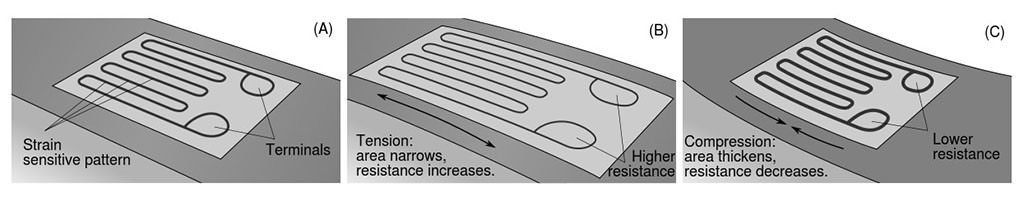
Semiconductor pressure sensors are sensitive, inexpensive, accurate, and repeatable. When a strain gauge, which is shown in, is used to measure the deflection of an elastic diaphragm or Bourdon tube, it becomes a component in a pressure transducer. Strain gauge-type pressure transducers are widely used.
Strain-gauge transducers are used for narrow-span pressure and for differential pressure measurements.
Essentially, the strain gauge is used to measure the displacement of an elastic diaphragm due to a difference in pressure across the diaphragm. These devices can detect gauge pressure if the low pressure port is left open to the atmosphere, or differential pressure if connected to two process pressures.
If the low pressure side is a sealed vacuum reference, the transmitter will act as an absolute pressure transmitter.
Bonded foil strain gauge, which has excellent stability and good overpressure protection is the very good choice to make wide and big pressure range transmitter.
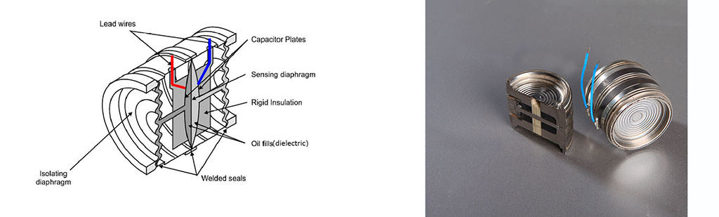
Pressure Sensor Technology of Capacitive
Capacitive pressure sensors use a thin diaphragm, usually metal or metal-coated quartz, as one plate of a capacitor.
The diaphragm is exposed to the process pressure on one side and to a reference pressure on the other. Changes in pressure cause it to deflect 29 and change the capacitance. The change may or may not be linear with pressure and is typically a few percent of the total capacitance.
The capacitance can be monitored by using it to control the frequency of an oscillator or to vary the coupling of an AC signal through a network. The electronics for signal conditioning should be located close to the sensing element to prevent errors due to stray capacitance. The schematic of a capacitive pressure sensor is shown in below.
Pressure Sensor Technology of Piezoresistive
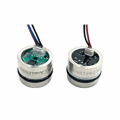
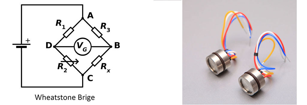
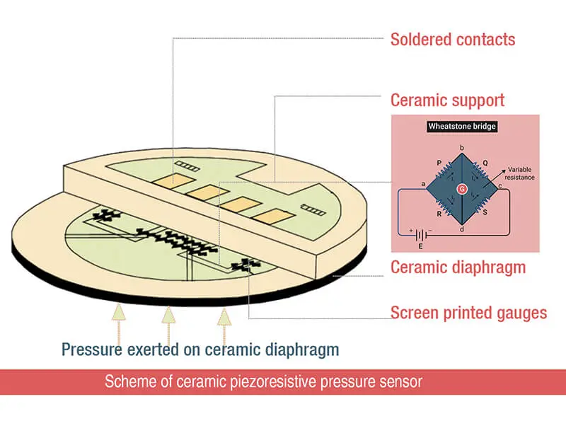
The piezoresistive pressure sensor elements consist of a silicon chip with an etched diaphragm and, a glass base anodically bonded to the silicon at the wafer level. The front side of the chip contains four ion-implanted resistors in a Wheatstone bridge configuration.
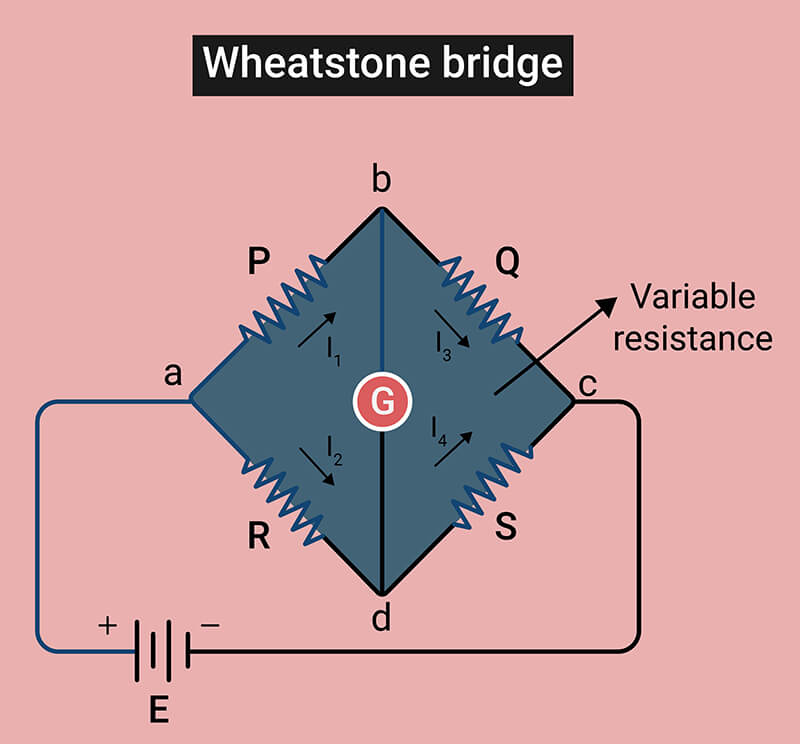
The resistors are located on the silicon membrane and metal paths provide electrical connections. When a pressure is applied, the membrane deflects, the piezoresistors change unbalancing the bridge.
Then a voltage develops proportional to the applied pressure (Sugiyama et al., 1983). Silicon piezoresitive sensors have been widely used for industrial and biomedical electronics. The piezoresitive sensors have excellent electrical and mechanical stability that can be fabricated in a very small size.
Characteristics comparison between Capacitive and Piezoresistive
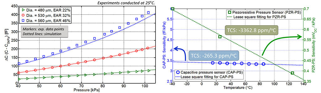
The pressure to capacitance difference relationship for three devices with various sizes in diaphragm and electrode areas is shown below, where Dia. represents the diaphragm diameter and EAR represents the ratio of electrode area to diaphragm area.
Comparing the experimental and simulation results, the deviations could be attributed to process variations in diaphragm dimensions. Extracting the sensitivity of the devices with least square fit, the errors are within 10%.
Comparing our device with a commercially available piezoresistive pressure sensor which has similar operating range, the preliminary result shows that when both sensors are not temperature compensated and for the temperature range we tested, the temperature coefficient of sensitivity of our capacitive device is 10 times better than the piezoresistive pressure sensor.
Advantage of Capacitive Sensing
Capacitance is a measure of energy stored between two conducting plates or electrodes holding an opposite charge.
Capacitance varies according to the strength of the charge, the distance between electrode plates, and the size of the plates. By keeping the charge between capacitor plates constant, you can tell how far one plate is from another by measuring the voltage between them.
Increase fluid pressure deflects the diaphragm (electrode plate), either closing or increasing the distance to the other plate, which changes the charge between plates. This simple approach proves both accurate and reliable, and offers many benefits over measuring pressure with strain gauges.
Advantage:
- Stable: Capacitive sensor/transmitter does not rely on an intermediate element, such as a strain gauge, to produce an output. They are also simpler and more reliable than bonded strain gauge elements because they require no adhesives, which can produce self-imposed strain from differential thermal expansion.
- Good compatibility: Media compatibility problems of integrated strain gauge transducers are avoided in capacitive transducers because the sensing diaphragm (electrode plate) can be constructed of stainless steel, ceramics, or other chemically non-reactive materials. They also accommodate a wide range of temperatures.
- Less error & high accuracy: Capacitive elements also produce a stronger output than strain gauge elements. Some signal conditioning is still required, but requires less amplification. Less amplification means error becomes a smaller portion of the output signal. Ultimately, accuracy is improved.
- EMI&RFI immune: EMI and RFI can generate stray fields, introducing electrical signals that controls may “confuse” with the actual transducer output. Unlike strain gauge elements, the high level output signal produced by capacitive type sensing elements is insensitive to low or moderate EMI and RFI, maintaining the integrity of the output.
- Reliability for millions cycles: Capacitive-sensing elements can also withstand millions of full scale pressure cycles without affecting accuracy because they do not suffer the same effects caused by the use of adhesives.
Performance of pressure sensing devices is affected by their design and technology. When compared to strain gauge sensors, capacitive sensors produce highly accurate, stable, EMI/RFI immune pressure transducers that meet performance requirements.
Disadvantage of Strain Gauge Sensing
Strain gauges are widely used to measure, electrically, how much a material shrinks or stretches in response to an applied force, torque, or stress. Strain gauge pressure-sensing elements use a diaphragm combined with a strain gauge to generate an output signal representative of the fluid pressure.
Disadvantage:
- Accuracy degradation: Bonded strain gauge sensing elements use an adhesive to attach the strain gauge to the diaphragm. Problems arise with this design because the adhesive often has a coefficient of thermal expansion different from the diaphragm and strain gauge.
- So if pressure remains constant, but temperature changes dramatically, the adhesive may expand or contract more than the diaphragm. The differential expansion could impose a strain on the strain gauge that would produce a different output signal even through the pressure did not change at all. Over time, this self-induced strain can permanently degrade accuracy.
- No rugged structure: Furthermore, millions of expansion and contraction cycles can weaken the adhesive bond. In most cases, this deteriorates accuracy, but in extreme cases–especially when aggravated by heavy vibration–the bond can fail completely, rendering the transducer useless.
- Incompatibility with adhesives: Integrated strain gauge sensing elements are designed with the strain gauge embedded in a diaphragm made of silicone or other material. While they avoid adhesives–and the problems associated with them– integrated strain gauge sensing elements compromise the fluid compatibility common with stainless steel diaphragms.
- Vulnerability: Diaphragms of silicone and other materials are attacked by a wide variety of chemicals found in industrial fluids. They also accommodate a narrower range of temperatures. Even if chemical incompatibility does not cause transducer failure, it can change the physical properties of the diaphragm, which degrades accuracy.
- EMI&RFI problem: Both types of strain gauges sensing elements produce relatively weak output signals. This means that weak or moderate EMI and RFI can degrade output.
Advantage of Piezoresistive pressure sensors
Piezoresistive based transducers rely on the piezoresistive effect which occurs when the electrical resistance of a material changes in response to applied mechanical strain.
In metals, this effect is realized when the change in geometry with applied mechanical strain results in a small increase or decrease in the resistance of the metal. The piezoresistive effect in silicon is due primarily to changes at the atomic level and is approximately two orders of magnitude larger than in metals.
As stress is applied, the average effective mass of the carriers in the silicon either increases or decreases (depending on the direction of the stress, the crystallographic orientation, and the direction of current flow).
This change alters the silicon’s carrier mobility and hence its resistivity. When piezoresistors are placed in a Wheatstone bridge configuration and attached to a pressure-sensitive diaphragm, a change in resistance is converted to a voltage output which is proportional to the applied pressure.
The piezoresistive pressure sensor also called Solid State Pressure Sensor, have excellent electrical and mechanical stability that can be fabricated in a very small size.
Advantage:
- Can eliminate the case-mounting effects on bias: Due to the small size of the pressure sensing silicon sensor, piezoresistive transducers may be constructed in a variety of packaging options that have been designed to eliminate the case-mounting effects on bias and sensitivity as well as low-frequency output generated by thermal expansion following proper installation. Piezoresistive SOI Sensors are fully integrated, monolithic structures.
- Smaller size can do more jobs: The final form factor of a transducer is one of the more important device attributes for many customers. piezoresistive sensor technology offer more flexibility in packaging than any other technology due to the extremely small size of the sensing element. Automotive applications include engine air, oil, cooling and fuel systems, brake systems, transmissions and general laboratory/developmental pressure measurements.
- Typical aerospace applications are scale-model and full-scale flight tests. Scale-model wind tunnel test articles, for instance, require the measurement of pressures on leading edge portions of the airframe where the radius can be under one tenth of an inch. In other applications, pressure measurements must be made in areas where the test article thickness is very thin and cannot be penetrated. Only piezoresistive pressure transducers may be manufactured to small enough sizes to support either of these installations.
- Extreme Environments Operability/Ruggedness: A majority of harsh environment commercial applications always use piezoresistive pressure transducers due to the small sensing element size (≈ 0.25 x 10⁻⁶ inch3 in volume), miniscule mass and robust construction.
- Piezoresistive pressure transducers do not require external amplifiers and special cables that other technologies need. Piezoresistive pressure transducers operate well in aircraft engine, nuclear, downhole, cryogenic, space, motor sports, and other extreme environment pressure measuring applications.
- Good temperature compensation ability: piezoresistive pressure sensors may be conditioned by the use of embedded digitally-programmed electronics. The programmable analog sensor conditioner circuitry is paired with sufficient memory to linearize the piezoresistive pressure sensor to better than ±0.1% of full scale at a constant temperature.
- Since the bridge resistance changes predictably temperature and piezoresistive pressure sensors are extremely repeatable, the embedded electronics may also be used to correct for bias and sensitivity shifts due to temperature. Piezoresistive pressure transducer temperature sensitivity may be controlled to within ±0.001% of full scale per degree Fahrenheit after electronic characterization of thepressure sensor is programmed into the embedded conditioning electronics
- Cost competitive: Installation costs of measurement systems dedicated to piezoresistive pressure transducers are generally lower than systems designed for piezoelectric pressure transducers. Transducers, cabling, and electronics for piezoresistive pressure transducers are each less than the cost of the corresponding piezoelectric pressure transducer system component. Fewer individual components are also a characteristic of piezoresistive pressure transducer installations.
Disadvantage of Piezoelectric-based sensing
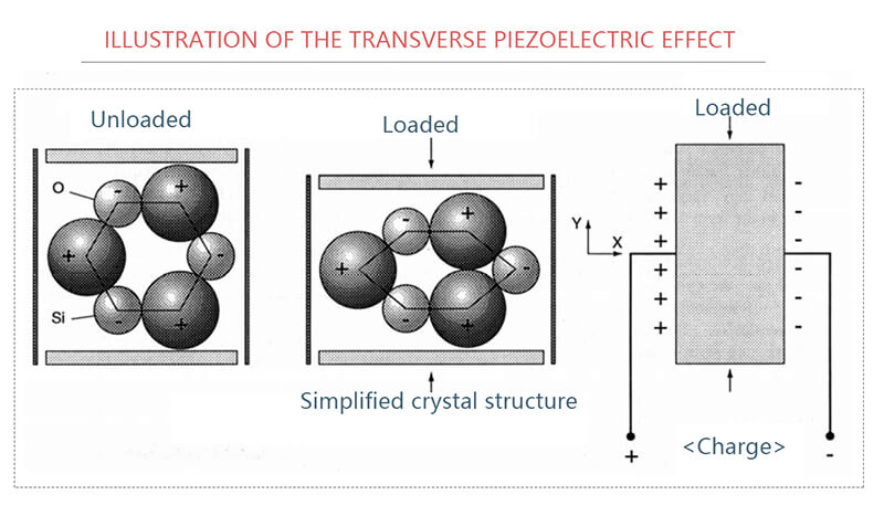
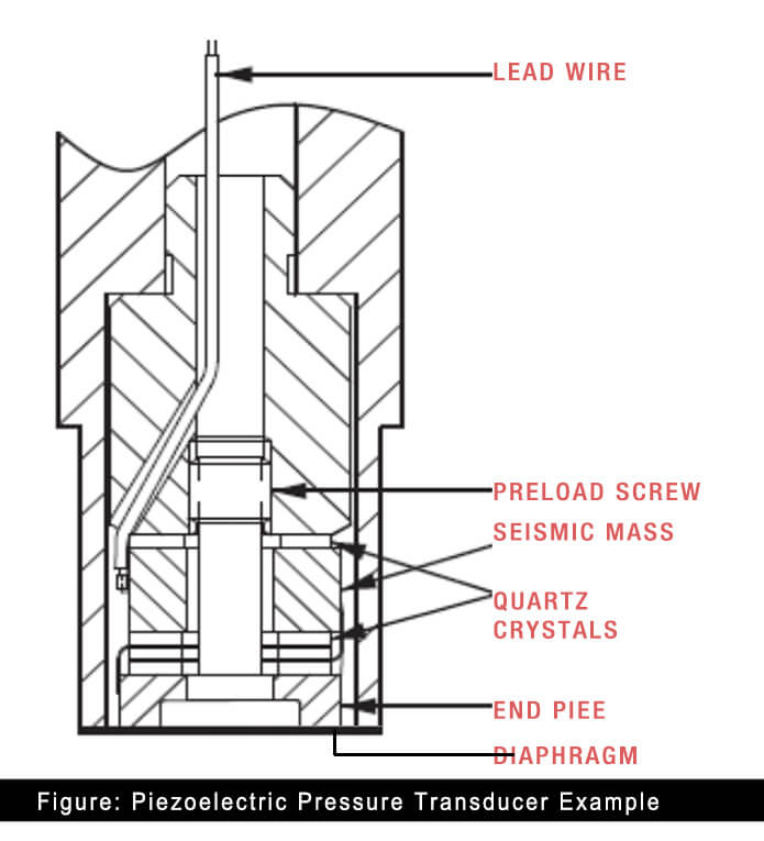
Piezoelectric-based transducers rely on the piezoelectric effect, which occurs when a crystal reorients under stress forming an internal polarization. This polarization results in the generation of charge on the crystal face that is proportional to the applied stress2. Quartz, tourmaline, and several other naturally occurring crystals exhibit a piezoelectric effect.
An electric charge proportional to the applied force is generated when a piezoelectric material is stressed by being coupled to an appropriate force summing device. Specially formulated ceramics can be artificially polarized to be piezoelectric with sensitivities 100 or more times higher than found in natural crystals3.
Unlike strain gage sensors, piezoelectric sensors require no external excitation. These sensors exhibit high output impedance and low signal levels; therefore, piezoelectric devices require the use of special equipment such as low-noise coaxial cable and charge amplifiers in the measurement chain.
Disadvantage:
- Susceptibility and inability: The high degree of stiffness provided by the compression mode enables the measurement of relatively high frequencies, but this construction worsens low frequency response due to thermally induced errors. Additionally, the compression mode construction is susceptible to a form of zero shift. Failure of the preload screw to maintain a constant force between the mass and the element will result in an output error. An abrupt change in the preload force may not be a one-time event and the resulting level shifts will be impossible to discern from pressure data.
- Construction limitation: Pressure transducers constructed using the compression mode can also be quite sensitive to installation. Virtually all miniature piezoelectric pressure transducers are constructed within a threaded assembly or a case requiring a threaded mounting adapter.
- If excessive torque is applied during transducer installation or if the sealing surface is improperly machined, the body of the sensor may become distorted and the sensitivity of the device will be affected. All piezoelectric pressure sensors are susceptible to some degree of degraded performance as a result of excessive mounting torque. The user is expected take special precautions to apply the manufacturer-recommended torque during installation.
- Big size if compare to piezoresistive technology: The smallest commercially available piezoelectric pressure transducer is 0.9 inches in length, 0.19 inches in diameter, and has an active sensing region 0.099 inches in diameter. However some isolated piezoresistive pressure transducer can be 0.375 inches in length, 0.055 inches in diameter, and having an active sensing element that is approximately 0.035” x 0.035”. This means that the smallest piezoresistive sensor is an order of magnitude smaller in volume, weight and sensing area than piezoelectric pressure sensor.
- Invalid to absolute pressure measurement: Piezoelectric pressure transducers are incapable of absolute pressure measurement. Users may therefore be unaware they are operating in a region outside the recommended pressure range. For all pressure transducers, it is best to limit dynamic pressure to frequencies of 30% of resonance frequency. Approaching the diaphragm resonant frequency will result in erroneous data and may lead to diaphragm failure.
- Accuracy decline in extreme temperature: All piezoelectric pressure transducers exhibit decreased insulation resistance when exposed to elevated temperature. This effect is due in part to the piezoelectric element, but the mineral insulated cable necessary to withstand the high temperatures typically contributes the largest error source. Specially constructed charge amplifiers must be used that are designed to operate with low impedance systems. These instruments capacitively couple the charge amplifier to the transducer/cable system to minimize the impact of potentially large offset voltages.
Features of Sputter deposited thin-film sensor
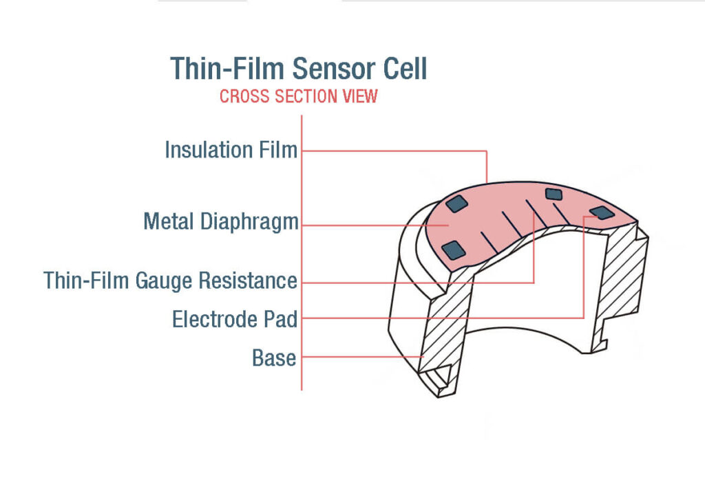
Sputter deposited thin film pressure sensor is a kind of Piezoresistive pressure sensors, difference exist that the thin-film sensor consists of a resistor pattern that is vaporized or sputter-deposited onto the force-summing element (the measuring diaphragm). In some transducers the resistors are not directly mounted on the diaphragm but are on a beam linked to the diaphragm by a push rod.
Many applications use a manufacturing process known as thin-film sputtering deposition. The typical sputtering process uses an ion beam to impact the surface of a sputter material such as gold, silver, or other metal or metallic oxide. In so doing, some of the sputter-material atoms get knocked into free space. The atoms bond with a substrate material to form a thin coating that may be only a few atoms thick.
- Integrity & Ruggedness: In the area of MEMS sensors, the sputtering-deposition technique lets manufacturers form sensors directly on the stressed substrate. The sensor becomes an integral part of the assembly, instead of being bonded to the stressed surface as are foil, resistive, and silicon strain gages. Combined with a Wheatstone bridge, thin-film sputtering-deposition strain gages eliminate many of the problems seen with these other measuring techniques, such as bonding separation or creep.
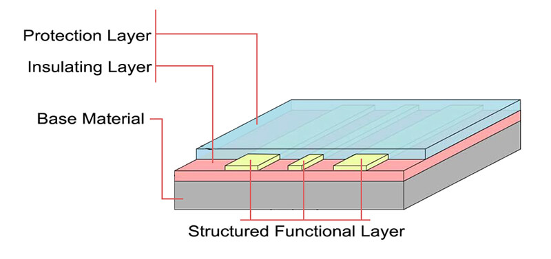
- Sandwiched structure: Almost any material can be used as a substrate for the sensor including stainless steel, Inconel, Hastaloy, aluminium, sapphire, and titanium. The process begins by preparing the surface of the substrate with diamond slurry to remove all surface pinholes and cracks.
- A dielectric layer is first deposited on the substrate to insulate circuit power from the underlying metal. Then a thin film of resistive alloy is sputtered over the dielectric layer. This layer is laser trimmed under power to produce the balanced resistors of the Wheatstone bridge. Wires attached to bonding pads applied to the circuit provide power egress. An encapsulation layer coats the final assembly to protect the thin film.
- Nearly perfect performance if made by sapphire: If made by sapphire, the sapphire pressure-gauge system is vacuum-filled and the resistor pattern forms a Wheatstone bridge. This system benefits from the elastic performance of the sapphire and its stable deformation properties. The result is a sensor with good repeatability, good stability, low hysteresis, and low drift. A high-gauge factor improves the resolution over traditional designs. The main disadvantages are low output level and high cost.
Additional Posts which may be of interest
- How to select Pressure Gauge?
- Pressure Switch V.S Pressure Transducer, what’s the difference?
- What is The Difference between Pressure Transducer and Pressure Transmitter?
- Basic Knowledge You Need to Know about Pressure Gauge
- 10 practices need to considerate before choosing pressure transducer
- 5 Pressure Sensor Working Principles You Need to Know