If you’ve ever found yourself staring at a spec sheet wondering whether you need a pressure transducer or a pressure transmitter, you’re not alone. Engineers across industries—from HVAC to hydraulics, from process control to mobile equipment—face this question regularly. The confusion is understandable because many vendors use these terms interchangeably, but there’s a real technical distinction that matters for your application.
Getting this choice right affects everything from installation costs to long-term reliability. Choose wrong, and you might end up with signal degradation, compatibility issues, or unnecessary expenses. This guide cuts through the confusion and gives you the practical knowledge to make the right decision for your specific needs.
The Core Difference: It’s All About the Output Signal
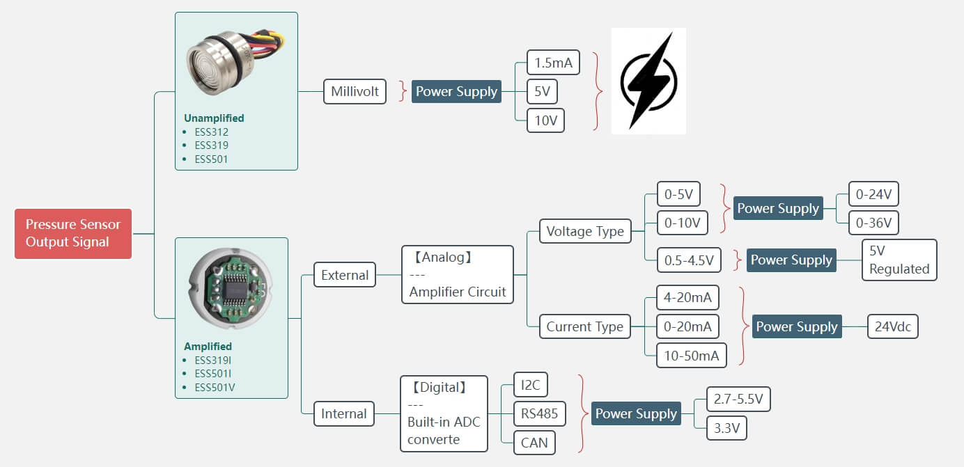
The main difference between a pressure transducer and a pressure transmitter comes down to the type of electrical signal they produce.
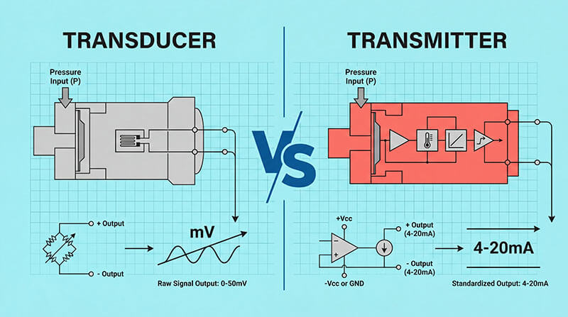
Pressure transducers output a low-level voltage signal, typically in millivolts (mV). The most common output is millivolt per volt (mV/V), meaning the output is proportional to the supply voltage. For example, with a 10mV/V transducer powered by 5VDC, you’ll get a 0-50mV output across the pressure range. These signals are not amplified, linearized, or temperature compensated—they’re raw signals straight from the sensing element.
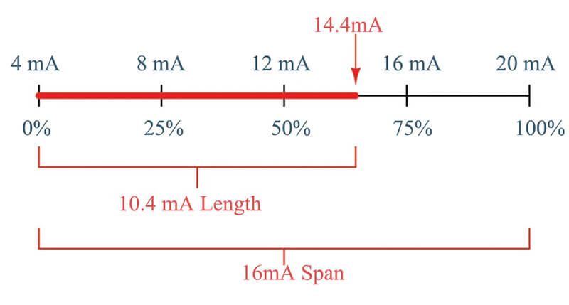
Pressure transmitters take things further. They include additional circuitry that amplifies, linearizes, and temperature-compensates the signal from the sensing element, then outputs a standardized industrial signal. The most common is the 4-20mA current loop, though you’ll also see 0-10V or 1-5V voltage outputs. The 4mA represents the minimum pressure (or zero), and 20mA represents the maximum pressure in your range.
This distinction isn’t just academic. It determines how far you can run your cables, how much electrical noise your system can tolerate, and what kind of receiving equipment you need.
| Feature | Pressure Transducer | Pressure Transmitter |
|---|---|---|
| Output Signal | Millivolt (mV) or low voltage (0-5V, 0-10V) | Current (4-20mA) or amplified voltage (1-5V, 0-10V) |
| Signal Conditioning | Minimal or none | Built-in amplification, linearization, temperature compensation |
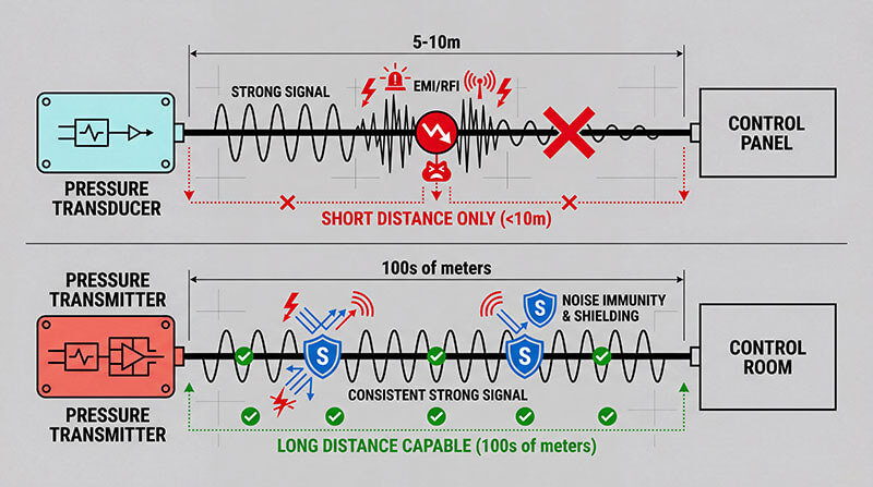
| Transmission Distance | Short (typically <10 meters) | Long (hundreds of meters without signal loss) |
| Noise Immunity | Lower - susceptible to EMI/RFI interference | Higher - current signals resist electrical noise |
| Power Requirements | Lower power consumption, can be battery-powered | Higher power consumption (typically 12-24VDC) |
| Wiring | 3-4 wires (separate power and signal) | 2-3 wires (power and signal can share wires) |
| Cost | Generally lower | Generally higher due to additional electronics |
| Fault Detection | Difficult (0V could mean zero pressure or broken wire) | Easy (signal below 4mA indicates fault) |
| Best Applications | Short-distance, low-noise environments, OEM equipment | Industrial plants, long cable runs, harsh electrical environments |
When to Choose a Pressure Transducer
Pressure transducers shine in specific scenarios where their characteristics become advantages rather than limitations.
Short-distance applications are ideal for transducers. If your sensor sits within a few meters of your control panel or data acquisition system, the low-level voltage signal travels just fine without degradation. Think of machinery where the sensor mounts directly on equipment and cables run cleanly to a nearby controller.
Low-power requirements make transducers perfect for battery-powered or portable systems. They typically consume less power than transmitters, which matters when you’re running on batteries or have strict power budgets. Mobile equipment, handheld test instruments, and remote monitoring systems often benefit from this efficiency.
OEM equipment integration frequently calls for transducers. When you’re building equipment where you control the entire signal path and can design proper shielding and short cable runs, transducers offer a cost-effective solution. The lower price point adds up when you’re manufacturing at volume.
Clean electrical environments let transducers perform reliably. In laboratory settings, test benches, or equipment cabinets where electrical noise is minimal and controlled, you don’t need the extra noise immunity that transmitters provide.
Custom signal conditioning needs sometimes favor transducers. If you’re designing a system with specialized amplification, filtering, or signal processing, starting with a raw mV signal gives you more flexibility than working with a pre-conditioned 4-20mA signal.
When to Choose a Pressure Transmitter
Pressure transmitters become essential when your application demands robust, reliable signal transmission over distance or through challenging conditions.
Long cable runs require transmitters. The 4-20mA current loop maintains signal integrity over hundreds of meters without degradation. Unlike voltage signals that drop across long wires, current remains constant regardless of cable length (within reasonable limits). Industrial plants, large facilities, and distributed systems rely on this capability.
Electrically noisy environments demand the noise immunity of current signals. Manufacturing floors with variable frequency drives, welding equipment, motors, and high-power machinery generate electromagnetic interference that corrupts voltage signals. Current loops resist this interference, delivering clean readings to your control system even when surrounded by electrical chaos.
Integration with PLCs and SCADA systems typically requires transmitters. Most industrial control systems expect 4-20mA inputs as standard. Using transmitters means direct connection without additional signal conditioning hardware. This simplifies installation, reduces component count, and improves reliability.
Built-in fault detection makes transmitters valuable for critical applications. The “live zero” at 4mA means any reading below 4mA immediately signals a problem—broken wire, power loss, or sensor failure. You don’t have to guess whether that zero reading represents zero pressure or a fault condition. This matters enormously in safety-critical systems or processes where undetected sensor failure could cause damage or downtime.
Temperature compensation and accuracy come standard with quality transmitters. The built-in electronics compensate for temperature effects on the sensing element, maintaining accuracy across your operating temperature range without external correction. For precision applications or wide temperature swings, this built-in compensation is worth the extra cost.
Two-wire loop-powered operation simplifies wiring in many installations. Many transmitters operate on the same two wires that carry the signal, reducing cable costs and installation complexity. This matters when you’re running dozens or hundreds of sensors across a facility.
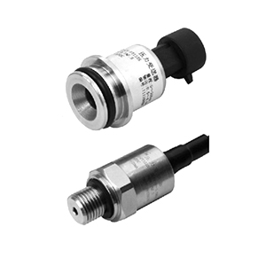
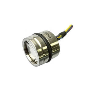
Pressure Sensor
A millivolt output signal generally. Millivolt (mV) output signal (also a general term for all pressure types); a device that measures pressure. The millivolt output signal can typically be used ten (10) to (20) feet away from the electronics without significant signal loss.
The signal is proportional to the supply. A 5VDC supply with a 10mV/V output signal produces a 0-50mV output signal. Older technologies such as bonded foil strain gage or thin film technology produce 2-3mV/V (millivolts per volt), whereas MEMS technology can produce 20mV/V reliably.
Millivolt output signals give the design engineer the flexibility to condition the output signal as their system needs it and can reduce package size and cost.
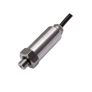
Pressure Transducer
An amplified voltage output typically. Transducers are voltage-output devices that can be used with simple signal conditioning but are more sensitive to electromagnetic interference.
The electrical resistance of the connecting cable can cause significant errors if the cable is long. They require three or four connecting wires to supply power and deliver the output signal.
Click to find more details about Why you need Millivolt Output Pressure Transducer?
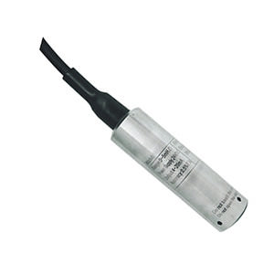
Pressure Transmitter
Always output 4~20mA signal. Transmitters are current-output devices and may have two or three wires. Where two wires are used to both receive power and transmit an output signal, significant cost savings can be made where long cables are needed.
They are frequently scaled to vary from 4 mA to 20 mA as the pressure varies from minimum to maximum. Thus the on-board electronics has to be capable of operating with a maximum current drain of less than 4 mA.
Being ‘current driven’, the in-built circuitry controls the voltage across the transmitters’ two terminals to ensure that the appropriate pressure-proportional current is maintained irrespective of line resistance up to a specified limit.
Thus these devices are very suitable for use with long cables and are much less susceptible to electromagnetic interference than voltage-output transducers. Sometimes called current loop or serial devices, additional displays at different locations can easily be included in the loop without degrading the output signal. Such devices normally suffer no significant degradation of signal output with distance.
Digital output transmitters normally contain a microprocessor which converts measured pressure values into digital codes which are transmitted to a remote receiver, or ‘host’, via wires, optical fibres or radio. There are a number of standard systems available, such as Fieldbus (IEC 1158) and HART, the latter having the facility to operate in combination with the more traditional 4 mA to 20 mA current-output systems.
Beyond supplying pressure values, digital transmission can include diagnostic information, status and alarms and can also facilitate remote reconfiguration of transmitters.
Once the difference can be described to the definition of signal output, the question can be set. Below is a general guideline on such terms and some advantage and disadvantage.

Pressure Transducer:
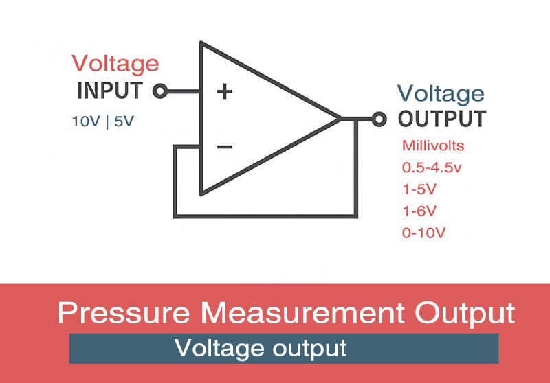
High level voltage or frequency output signal including 0.5 to 4.5V ratiometric (output signal is proportional to the supply), 1-5V and 1-6kHz.
These output signals should be used within twenty (20) feet of the electronics. Voltage output signals can offer low current consumption for remote battery operated equipment. Supply voltages are typically from 8-28VDC, except for the 0.5-4.5V output, which requires a 5VDC regulated supply.
Older voltage output signals, such as 0-5V, do not have a “live zero” where there is signal when the sensor is at zero pressure. The risk is that the system does not know the difference between a failed sensor with no output and zero pressure.
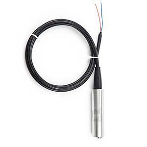
Pressure Transmitter:
Current output signal, i.e. 4-20mA (4 to 20mA), the current, rather than the voltage, is measured on the device, rather than the voltage; EastSensor pressure transmitters also have many types of two wire devices (red for supply, black for the ground). 4-20mA pressure transmitters offer good electrical noise immunity (EMI/RFI), and will need a power supply of 8-28VDC.
Because the signal is producing current, it can consume more battery life if operating at full pressure.
Pressure Transducers are available with a variety of voltage output options.
With advances in controllers that receive the transducer signal, there is more flexibility in the marketplace. There are minor differences between many of the output options on the market place. While some developed to maintain competitive advantages via customized products, others have solid reasoning.
The outputs reviewed here are all powered by a minimum of 10VDC (0-10V and 1-10V outputs need 12VDC). A 0.5-4.5V ratiometric output signal is traditionally powered by a 5VDC regulated supply, yet other variations are possible. In a similar way, millivolt output signals have their own unique features and benefits. The following is a brief introduction to amplified voltage pressure transducers.

Zero based output
Traditional pressure transducer outputs include 0-5V and 0-10V signals. Popularized in Europe, zero based output signal produce no output signal at zero pressure in a standard gauge pressure transducer.
Transducers are offered in three wire and four wire configurations with zero based output signals. The advantage of the 0-10V signal is that it has twice the span as the 0-5V. The main disadvantage to any zero-based output signal is that there is no signal with zero pressure.
If the transducer has a cut wire, broken sensing element, or electronics that received an over-voltage, the sensor will produce no signal, thus no way to know of a problem. If we assume that the pressure transducer is measuring water pressure, it will produce a 0V signal when there is no pressure in the line.
When pressure is sensed, it will signal the pump to act. Since the sensor at 0V is the same in fault conditions and at no pressure, there is no way to distinguish between the two. The pump would not know to run, and could cause a flooding condition.
Voltage at zero pressure
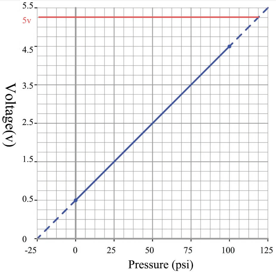
There are many variations and custom options for pressure transducers with an output signal at 0 PSI. For example, EastSensor offers 1-3V, 1-5V (for Automotive Industry), and 0.5-4.5V. The 1-5V output signal is most popular in the industry. There is the safety feature of having a 1 volt output signal at zero pressure and a 4 volt span for pressure measurement. 1-3V and 1-5V output signals are popular among engineers who prefer a voltage span similar to the zero based outputs above, but with the signal at zero pressure. The 0.5-4.5V output signal is somewhat unique.
For remote telemetry applications, current consumption is a common factor. Because lithium-ion batteries or solar panels create power in remote oil fields and on construction site equipment, having a low power supply voltage and low current consumption extend the service life of the pressure transducer.
The 0.5V 0PSI signal gives enough indication that the transducer is working. The span to 4.5V gives enough resolution to accurately measure the pressure or level
Common Mistakes to Avoid
Engineers sometimes make predictable errors when selecting pressure measurement devices.
Assuming the terms are interchangeable leads to ordering the wrong device. Always verify the output type rather than relying on the vendor’s terminology. Check the spec sheet for “4-20mA” or “mV/V” to confirm what you’re actually getting.
Ignoring cable length causes signal problems. Running a transducer’s mV signal 50 meters through a noisy plant environment will give you garbage readings. If your installation requires long cables, use a transmitter or plan for local signal conditioning.
Forgetting about electrical noise results in unstable readings. That voltage output transducer might work fine on your test bench but fail miserably when installed next to a VFD or welding equipment. Consider your actual installation environment, not just your lab conditions.
Overlooking power supply requirements creates installation headaches. Ordering transducers that need regulated 5VDC when your system provides 24VDC means adding power supplies. Verify compatibility with your available power before ordering.
Not considering total system cost leads to false economies. That cheaper transducer might require an expensive signal conditioning module, separate power supply, and shielded cable that costs more than just buying a transmitter in the first place. Calculate the complete installation cost, not just the sensor price.
Making Your Decision: A Practical Framework
Here’s a straightforward decision framework based on your application requirements:
Start with your signal transmission distance. If it’s under 10 meters in a clean environment, transducers are viable. Over 10 meters or in noisy environments, lean toward transmitters.
Consider your receiving equipment. If you’re connecting to a PLC, SCADA system, or industrial controller, check what inputs it has. Most expect 4-20mA, making transmitters the natural choice. If you’re building custom electronics or using data acquisition systems, you have more flexibility.
Evaluate your electrical environment. Walk through your installation location. Are there motors, drives, welding equipment, or other noise sources nearby? If yes, transmitters provide better immunity. Clean environments allow transducers.
Factor in your power availability. What voltage is available at the sensor location? Can you provide regulated low voltage for transducers, or is it easier to use transmitters with wide supply voltage ranges?
Think about fault detection needs. For critical applications where you must know immediately if a sensor fails, transmitters with their 4mA live zero provide clear fault indication. For less critical monitoring, transducers may suffice.
Calculate total installed cost. Price the sensor, cables, signal conditioning (if needed), installation labor, and any additional components. Sometimes the more expensive transmitter costs less overall because it eliminates other components.
Why Choose a Manufacturer Who Understands Both
Working with a manufacturer who produces both pressure transducers and transmitters gives you significant advantages. You get unbiased recommendations based on your actual needs rather than being pushed toward whatever the vendor happens to make. You benefit from deep expertise in pressure sensing technology regardless of the output format. And you have flexibility as your requirements evolve—starting with transducers for OEM equipment and moving to transmitters for field installations, all from the same trusted source.
At our facility, we manufacture both pressure transducers and transmitters using the high-quality sensing elements. This means you get consistent accuracy and reliability whether you choose a transducer for your compact equipment or a transmitter for your industrial installation. Our R&D team stays current with both technologies, continuously improving performance, reducing size, and expanding capabilities.
Get the Right Pressure Measurement Solution for Your Application
The difference between pressure transducers and transmitters comes down to practical engineering choices about signal type, transmission distance, noise immunity, and system integration. Neither is universally better—each excels in specific applications.
Understanding these differences helps you specify the right device the first time, avoiding costly mistakes and ensuring reliable pressure measurement in your system. Whether you need the compact simplicity of a transducer or the robust long-distance capability of a transmitter, the key is matching the technology to your actual installation requirements.
Ready to discuss your specific pressure measurement needs?
Our engineering team can help you select the optimal solution—whether that’s a custom pressure transducer, a standard transmitter, or a specialized design for your unique application. We offer:
- Custom pressure ranges from vacuum to 10,000+ PSI
- Multiple output options including mV/V, 0-5V, 0-10V, 1-5V, and 4-20mA
- Specialized designs for harsh environments, high temperatures, corrosive media
- Fast prototyping to validate designs before production
- Volume manufacturing with consistent quality and competitive pricing
- Technical support from engineers who understand real-world applications
Contact our engineering team today to discuss your pressure measurement requirements. We’ll help you choose between transducers and transmitters based on your specific application, not just what’s on the shelf. Get reliable, accurate pressure measurement that integrates seamlessly with your system.
Have questions about pressure transducers vs transmitters? Our engineering team has decades of experience designing pressure measurement solutions for industries ranging from aerospace to industrial automation. Reach out today for expert guidance on your specific application.
Additional Posts which may be of interest
- How to select Pressure Gauge?
- Pressure Switch V.S Pressure Transducer, what’s the difference?
- How sensor has been rocking our world?
- What’s the role of smart sensors in Industry 4.0?
- Basic Knowledge You Need to Know about Pressure Gauge
- 10 practices need to considerate before choosing pressure transducer