Digital pressure sensor

Digital pressure sensor

Contents
2
3

Introduction

A digital pressure sensor is a device that measures and detects the pressure of a fluid or gas and converts it into a digital signal for further processing or display. It typically consists of a sensing element, which can be a piezoresistive, capacitive, or piezoelectric element, and an electronic circuitry that converts the analog pressure measurement into a digital output.

The digital signal can then be transmitted to a computer, microcontroller, or other electronic devices for monitoring, control, or analysis.

Digital pressure sensors are the devices that convert physical pressure into a digital signal that can be interpreted by electronic systems. They are integral components in various applications across industries, including automotive, aerospace, medical, HVAC, and industrial process control.

In this guide, we will discuss the most popular type of digital output for pressure sensor, you will find the highlight features including I2C, RS485 and CAN Bus protocols, for details content, you can also browse our exact blog pages.

Technical Specifications of digital pressure sensor

Pressure Range: The pressure range indicates the minimum and maximum pressure that the sensor can accurately measure.

For example, a sensor might have a range from 0 to 100 PSI (pounds per square inch), or from -15 to 15 PSI for differential pressure applications.

Accuracy

This indicates how closely the sensor’s measurements match the true pressure. It’s usually expressed as a percentage of full scale (FS), such as ±0.25% FS. This means that if a sensor has a range of 0 to 100 PSI, the readings can deviate by as much as ±0.25 PSI from the actual pressure.

Resolution

The smallest change in pressure that the sensor can detect. For a high-resolution sensor, this might be as small as 0.001 PSI.

Output Interface

The type of digital protocol used to communicate with the sensor. Common types are I2C and SPI, which are serial communication protocols used for short-distance, intra-board communication.

How digital pressure sensor work

Digital output pressure sensors typically contain a piezoresistive element, a type of resistor that changes its resistance based on the pressure applied to it. This resistance change is converted into a voltage change by a circuit within the sensor.

This analog voltage signal is then converted into a digital signal by an Analog to Digital Converter (ADC). The ADC resolution, often 12, 16, 24 or even 32 bits, determines the smallest pressure change that can be detected by the sensor.

Digital pressure sensor I2C RA485 CAN Bus

The digital signal is then sent to a microcontroller or other digital system using a digital communication protocol. The receiving system uses this digital signal to determine the pressure based on calibration data provided by the sensor manufacturer.

Advantages of digital output signal

1, Reliability

Digital signals are less susceptible to noise and interference than analog signals, which can improve the reliability of the pressure readings, especially over long distances or in noisy environments.

2, Integration

Digital sensors are easier to integrate with other digital systems, as they can communicate directly with microcontrollers and microprocessors.

3, Calibration

Many digital pressure sensors have built-in temperature compensation and calibration data, which can improve accuracy across a wide range of operating conditions.

4, Programmability

Some digital pressure sensors allow users to program the pressure range, output data rate, and other parameters, providing flexibility for different applications.

Types of digital pressure sensor

Digital pressure sensors are commonly used in various applications such as industrial automation, automotive systems, medical devices, and consumer electronics.

Here are some common types of digital interfaces for pressure sensors that Eastsensor produce, also the most regular types with different speed and range from short distance to very long remote data transmit.

1, I2C (Inter-Integrated Circuit) Sensors:

These sensors use the I2C protocol, a serial communication protocol allowing multiple devices to communicate with each other over the same bus.

I2C bus with a single master and three slaves

2, SPI (Serial Peripheral Interface) Sensors:

These sensors use the SPI protocol, another type of serial communication protocol known for its high speed.

3, CAN (Controller Area Network) Sensors:

These sensors use the CAN protocol, a robust communication protocol often used in automotive applications.

CAN-Bus-wiring-01

4, RS485 Modbus:

RS485 is a standard for serial communication transmission of data. It uses differential signaling, which means it transmits information using two complementary signals. This allows it to reject common-mode noise, making it robust in industrial environments.

RS-485 devices with 4 contacts

5, 4-20mA HART

The 4-20mA signal is a standard in many industries for analog signals over long distances.

HART (Highway Addressable Remote Transducer) is a protocol that can be used in conjunction with the 4-20mA standard. It allows for two-way field communication, meaning it can transmit and receive more than one signal over the same wires.

What is the advantage and trade-off of each type?

I2C (Inter-Integrated Circuit):

  • Speed/Max Bit Rate: Standard mode up to 100 kbit/s, Fast mode up to 400 kbit/s, and High-Speed mode up to 3.4 Mbit/s.
  • Number of Pins: 2 (SDA for data, SCL for clock).
  • Data Transfer Distance: Typically less than 1 meter.
  • Noise Immunity: Moderate due to voltage level signaling.
  • Inter-Connectivity: Can connect multiple devices (both masters and slaves) on the same bus.
  • Typical Application: Short-distance, intra-board communication.
  • Pros: Simplicity, flexibility with multiple masters and slaves, and built-in addressing.
  • Cons: Limited distance and speed, no error checking.

SPI (Serial Peripheral Interface):

  • Speed/Max Bit Rate: Typically up to 10 Mbit/s, can be higher depending on the specific device.
  • Number of Pins: 4 (MISO, MOSI, SCK, and SS).
  • Data Transfer Distance: Typically short, within a single circuit board.
  • Noise Immunity: Low, due to the absence of differential signaling.
  • Inter-Connectivity: Single master with multiple slaves using separate chip select lines.
  • Typical Application: Short-distance, high-speed applications.
  • Pros: High speed, full duplex communication.
  • Cons: Requires more pins than I2C, not suitable for long distance, no error checking.

CAN (Controller Area Network):

  • Speed/Max Bit Rate: Up to 1 Mbit/s at short distances, lower at long distances.
  • Number of Pins: 2 (CAN_H and CAN_L for differential signaling).
  • Data Transfer Distance: Up to 40 meters at 1 Mbit/s, can be extended to 1 kilometer at lower speeds.
  • Noise Immunity: High, due to differential signaling and error checking.
  • Inter-Connectivity: Multiple devices on the same bus using message-based communication.
  • Typical Application: Vehicle network (automotive), industrial automation.
  • Pros: Robust error handling, excellent noise immunity, great for networking multiple devices.
  • Cons: More complex than I2C or SPI, lower speed.

RS-485

  • Speed/Max Bit Rate: Up to 10 Mbit/s.
  • Number of Pins: 2 (A and B for differential signaling).
  • Data Transfer Distance: Up to 1.2 kilometers.
  • Noise Immunity: High, due to differential signaling.
  • Inter-Connectivity: Multi-point systems, up to 32 devices on the same bus.
  • Typical Application: Long-distance, noisy environments, industrial control systems.
  • Pros: Long-distance capability, high speed, excellent noise immunity.
  • Cons: Half-duplex, requires careful management of bus idle state, more complex than I2C or SPI.
ProtocolDistanceSpeed/Max Bit RatePinsNoise ImmunityInter-Connectivity
NFCUp to 0.1 mUp to 424 kbit/sN/ALowPoint-to-point
I2CUp to 2 mUp to 3.4 Mbit/s2ModerateMulti-master, multi-slave
TTLUp to 2 mTens of Mbit/s1 per signalLowDepends on implementation
ParallelUp to 3 mHundreds of Mbit/s20-50ModeratePoint-to-point
USBUp to 5 mUp to 20-40 Gbit/s4--24Very HighPoint-to-point
HDMIUp to 5 mUp to 48 Gbit/s19Very HighPoint-to-point
SPIUp to a few metersUp to 50 Mbit/s4ModerateSingle-master, multi-slave
UARTUp to 10 mUp to 5 Mbit/s2LowPoint-to-point
RS232Up to 15 mUp to 115.2 kbit/s9LowPoint-to-point
SDI-12Up to 100 m1200 bit/s3ModerateMulti-drop
CANUp to 1000 mUp to 1 Mbit/s2Very HighMulti-master
RS422Up to 1200 mUp to 10 Mbit/s4HighPoint-to-point, multi-drop
RS485Up to 1200 mUp to 10 Mbit/s2 or 4Very HighMulti-drop
Fieldbus FoundationUp to 1900 mUp to 31.25 kbit/s2Very HighMulti-drop
4-20mA HARTUp to 2000 m1200 bit/s2Very HighMulti-drop

Digital Pressure sensor output

Which is best for automotive industry?

In automotive applications, the Controller Area Network (CAN) bus protocol is widely recognized as the best choice for sensor output communication. This assertion is based on several technical specifications and the requirements of automotive systems:

  • Reliability
  • Multi-Device Communication
  • Error Checking
  • Real-Time Capability
  • Standardization
  • Click to check details of: CAN Bus Pressure Sensor

While CAN bus is the standard, other communication protocols can also be used in automotive applications.

CAN DATA FRAME

For example, Local Interconnect Network (LIN) may be used for less critical systems due to its lower cost, and FlexRay may be used in systems requiring higher data rates or deterministic behavior.

Ethernet (via BroadR-Reach or Automotive Ethernet) is also becoming more popular in vehicles, especially for high-bandwidth applications like infotainment systems or advanced driver-assistance systems (ADAS).

In terms of sensor output, while digital protocols like CAN are often preferred for their noise immunity and integration with digital systems, analog sensors (like those using the 0.5-4.5V or 4-20mA standards) can still be used in certain automotive applications, where the simplicity and lower cost of analog sensors can be beneficial.

However, these are typically used in less critical systems and are increasingly being replaced by digital sensors.

Which is commonly used in industry control system?

In industrial control systems, a variety of digital output protocols are used for pressure sensors. The choice of protocol often depends on the specific requirements of the system, such as the need for long-distance transmission, networking capabilities, or resistance to electrical noise.

1. Modbus:

Modbus is a serial communication protocol commonly used for connecting industrial electronic devices. It’s simple, robust, and allows for communication between many devices over long distances, making it a popular choice for industrial applications.

2. HART (Highway Addressable Remote Transducer): HART is a widely used communication protocol in process industries. It’s designed to superimpose digital communication signals onto the traditional 4-20mA analog signal used in these industries, allowing for two-way field communication and enabling additional features like device configuration and diagnostics.

Here are some key points about 4-20mA HART:

  • HART can send digital data over the same wires as the 4-20mA analog signal. This allows for additional information beyond just the primary sensor reading to be transmitted, such as device status, diagnostics, or additional sensor readings.
  • HART communication can support up to two masters (e.g., a handheld device for field configuration and a control system) and multiple slaves (the field devices).
  • It is widely used in process control industries for field device communication, enabling configuration, calibration, and diagnostics.

3. Profibus:

Profibus (Process Field Bus) is another common protocol in process automation industries. It provides high-speed communication and supports a wide range of devices, from simple field devices to complex automation systems.

4. CAN (Controller Area Network): While it’s best known for its use in automotive applications, CAN is also used in some industrial control systems, especially in machine control where a real-time response is required.

5. Zigbee: Zigbee is a high-level communication protocol used to create personal area networks with small, low-power digital radios. It’s often used in wireless pressure sensors in applications such as home automation, medical device data collection, and other low-power, low-bandwidth needs.

Click to download datasheet of: EST345Z-Zigbee Wireless Pressure Transmitter

Which is for low-speed communication between sensor and computer?

For low-speed communication between a sensor and a computer, the I²C (Inter-Integrated Circuit) and SPI (Serial Peripheral Interface) protocols are commonly used.

Both are synchronous serial communication protocols developed for short-distance, low-speed communication between integrated circuits.

I2C Pressure Sensor-SDA-SCL-2

I²C

  • I²C is a two-wire interface, using one wire for data (SDA) and one for clock (SCL).
  • It supports multiple master and slave devices on the same bus.
  • It is typically used for lower speed applications (standard modes support up to 100 kbit/s and 400 kbit/s, but a high-speed mode can support up to 3.4 Mbit/s).
  • It includes built-in support for addressing and acknowledgement, simplifying communication between devices.
  • It is often used for connecting peripheral hardware to a microcontroller, such as sensors, display drivers, or memory chips.

SPI

  • SPI uses a four-wire interface, with separate wires for data in (MISO), data out (MOSI), clock (SCK), and a chip select line for each slave (SS).
  • It only supports one master device but can support multiple slaves.
  • It can generally support higher speeds than I²C (up to several Mbit/s), but the actual speed is determined by the master device and the length and quality of the connections.
  • It doesn’t include built-in addressing or acknowledgement, making the protocol simpler but requiring additional handling in software if these features are needed.
  • Like I²C, it is often used for connecting peripheral hardware to a microcontroller.
ESS319 I2C Pressure sensor

ESS319-IIC  Pressure Sensor ( I2C ) Module

ESS501-I2C ceramic pressure sensor thick film ceramic

ESS501-IIC Pressure Sensor ( I2C ) Module

I2C Pressure Sensor

I2C Pressure Sensor

Contents
2
3

Introduction

The Role of I2C Protocol in Pressure Sensor Applications

As an experienced electrical engineer, I can confidently say that the Inter-Integrated Circuit (I2C) protocol plays a crucial role in pressure sensor applications.

I2C is a serial communication protocol that allows multiple devices to communicate with each other over a simple two-wire interface. This simplicity makes it a popular choice for interfacing with pressure sensors.

The I2C protocol allows for high-speed, bi-directional communication between the sensor and the microcontroller. This is particularly important in applications where real-time pressure data is required, such as in

  • Industrial automation
  • Automotive systems
  • Weather monitoring stations

The I2C protocol is also highly scalable, allowing for the integration of multiple pressure sensors on the same I2C bus. This is beneficial in applications where pressure needs to be monitored at multiple points simultaneously, such as in HVAC systems or in complex hydraulic systems.

Overview of I2C Communication Basics

The I2C communication protocol operates over two lines:

  • Serial Data Line (SDA)
  • Serial Clock Line (SCL)

The SDA line is used for transferring data, while the SCL line provides the clock signal that synchronizes the data transfer.

I2C Pressure Sensor-SDA-SCL-2

Each device on the I2C bus has a unique address, which allows the microcontroller to communicate with specific devices. In the case of pressure sensors, the I2C address is typically specified by the manufacturer and can sometimes be configured by the user.

Data transfer over the I2C bus occurs in 8-bit packets, with each packet followed by an acknowledgment bit. This acknowledgment bit allows the sender to confirm that the data has been received correctly, improving the reliability of the communication.

The I2C protocol also supports multi-master communication, meaning that multiple microcontrollers can control the same pressure sensor. This is useful in complex systems where redundancy is required, or where multiple microcontrollers need to access the same pressure data.

ParameterDescriptionExample
ProtocolSerial communication protocol used for interfacing with pressure sensorsI2C
LinesTwo lines used for communication: SDA (data) and SCL (clock)SDA, SCL
AddressingEach device has a unique address for communication0x76 (for a specific pressure sensor)
Data TransferData is transferred in 8-bit packets, followed by an acknowledgment bit8-bit data + 1-bit acknowledgment
Multi-Master SupportMultiple microcontrollers can control the same sensorUseful in complex systems requiring redundancy
SpeedI2C supports several speed modesStandard-mode (100 kbit/s), Fast-mode (400 kbit/s), High-speed mode (3.4 Mbit/s)
Noise ImmunityI2C uses a wired-AND function for noise immunityNoise is filtered out if it doesn't match the AND function
Power ConsumptionI2C is a low-power protocolIdeal for battery-powered devices
ScalabilityMultiple devices can be connected to the same I2C busUp to 112 devices on the same bus
Error CheckingI2C includes built-in error checking with acknowledgment bitsEnsures reliable data transfer
Transmission DistanceI2C is typically used for short-distance communicationSuitable for distances up to a few meters

Principles of I2C Communication in Pressure Sensors

I2C Message Structure and Data Transfer

When it comes to the I2C message structure, it’s important to understand that each I2C transaction consists of a start condition, an address frame, one or more data frames, and a stop condition.

The start condition is a unique signal that marks the beginning of a transaction. It’s generated by the master device and is followed by the address frame.

The address frame contains the 7-bit address of the device the master wants to communicate with, followed by a read/write bit. If the bit is high, the master wants to read from the device. If it’s low, the master wants to write to the device.

The data frames follow the address frame. Each data frame contains 8 bits of data, followed by an acknowledgment bit. The acknowledgment bit is used to confirm that the data has been successfully received.

The stop condition marks the end of the transaction and is generated by the master device.

IC2 communication

The data frames would typically contain the pressure data that the pressure sensor is measuring. This data can then be read by the microcontroller and used in whatever application the sensor is being used for.

Importance of Unique Device Addressing and Multi-Master Capability

Unique device addressing is a key feature of the I2C protocol that allows multiple devices to share the same I2C bus.

Each device on the bus has a unique address, which the master device uses to communicate with specific devices. This is particularly important in pressure sensor applications where multiple sensors might be used to monitor pressure at different points in a system.

The multi-master capability of the I2C protocol is another important feature.

This allows multiple master devices to control the same pressure sensor. In a complex system, this can provide redundancy and allow for more flexible system design.

I2C Pressure Sensor-Pins-in-Raspberry-Pi-Pico

For example, if one microcontroller fails, another can take over its duties without any disruption to the system.

Advantages of I2C Pressure Sensors

Simplified Wiring and Reduced System Complexity

One of the key advantages of I2C pressure sensor is their ability to simplify wiring and reduce system complexity. The I2C protocol operates over a simple two-wire interface, with one wire for data (SDA) and the other for clock (SCL). This is significantly less than what’s required for parallel communication protocols, which can require upwards of 8 data lines plus additional control lines.

This simplified wiring scheme not only reduces the physical complexity of the system, but it also reduces the cost and time associated with wiring and troubleshooting.

Furthermore, it allows for a more compact and lightweight design, which can be particularly beneficial in space-constrained applications such as drones or handheld devices.

High Noise Immunity and Improved Signal Quality

Another advantage of I2C digital output pressure sensors is their high noise immunity.

The I2C protocol uses a wired-AND function for noise immunity, which means that noise is filtered out if it doesn’t match the AND function. This can significantly improve the signal quality, especially in noisy environments or over long transmission distances.

In addition, the use of digital signals means that the data is less susceptible to degradation compared to analog signals. This can result in more accurate and reliable pressure readings, which is crucial in applications such as medical devices or aerospace systems where precision is paramount.

Compatibility with a Wide Range of Devices

Finally, I2C pressure sensor is compatible with a wide range of devices.

The I2C protocol is widely supported by many microcontrollers and single-board computers, including popular platforms like Arduino and Raspberry Pi. This makes it easy to integrate I2C pressure sensors into a variety of systems and applications.

I2C Pressure Sensor-Arduino vs raspberry pi

Furthermore, the scalability of the I2C protocol allows for the integration of multiple pressure sensors on the same I2C bus. This can be beneficial in applications where pressure needs to be monitored at multiple points simultaneously, such as in HVAC systems or complex hydraulic systems.

Implementing I2C Pressure Sensor in Common Applications

Industrial Process Control and Automation

In the realm of industrial process control and automation, I2C digital output pressure sensors play a pivotal role. These industries often require real-time monitoring and control of various parameters, including pressure, to ensure the smooth and efficient operation of processes.

For instance, in a hydraulic system, pressure sensors can provide crucial data about the pressure of the fluid in the system. This data can be used to control valves, pumps, and other components to maintain optimal system performance.

The I2C protocol’s ability to support multiple devices on the same bus allows for the monitoring of pressure at various points in the system simultaneously, providing a comprehensive overview of the system’s status.

I2C bus with a single master and three slaves

Environmental Monitoring Systems

Environmental monitoring systems are another common application for I2C digital output pressure sensors.

These systems often require the monitoring of atmospheric pressure as part of weather forecasting or climate research.

In these applications, the high noise immunity and improved signal quality of I2C pressure sensors can provide accurate and reliable pressure readings, even in challenging environmental conditions.

Furthermore, the low power consumption of the I2C protocol makes it ideal for battery-powered devices, such as portable weather stations or remote sensing devices.

Automotive and Aeronautical Applications

In automotive and aeronautical applications, pressure sensors are used for a variety of purposes, from monitoring tire pressure to measuring the pressure in hydraulic braking systems.

In aircraft, I2C pressure sensors can also be used to monitor cabin pressure and engine oil pressure. In these applications, the robustness and reliability of I2C digital output pressure sensors are of paramount importance.

The high noise immunity of the I2C protocol can ensure reliable communication even in the presence of the electrical noise commonly found in automotive and aeronautical environments.

Furthermore, the ability to connect multiple sensors to the same I2C bus can simplify system design and reduce wiring complexity.

Challenges and Limitations of I2C Pressure Sensor

Limitations on Communication Speed and Cable Length

While the I2C protocol offers many advantages, it does come with certain limitations.

One of these is the limitation on communication speed and cable length.

The I2C specification defines several speed modes, with the fastest being High-speed mode at 3.4 Mbit/s. However, achieving this speed requires careful design and shorter cable lengths.

As the length of the cable increases, the capacitance of the I2C bus increases, which can limit the speed at which data can be transferred.

In practice, I2C is typically used for communication over distances of up to a few meters.

For longer distances, other communication protocols such as RS-485 or Ethernet may be more suitable.

Potential for Interference from Other I2C Devices

Another challenge when using I2C pressure sensors is the potential for interference from other I2C devices.

Because the I2C bus is a shared medium, all devices on the bus can potentially interfere with each other. This is particularly a concern in multi-master systems, where multiple devices can attempt to control the bus at the same time.

To mitigate this, the I2C protocol should include arbitration and collision detection mechanisms.

However, these mechanisms can add complexity to the system and may not completely eliminate the risk of interference, especially in systems with a large number of I2C devices.

In Eastsensor, we provide two kinds of I2C output sensors

ESS319-I2C Digital Output Pressure Sensor Φ19mm Eastsensor Technology

Conclusion

As a pressure measurement & control engineer, I can’t stress enough the importance of understanding and implementing I2C technology in pressure sensing applications.

The I2C protocol’s simplicity, scalability, and robustness make it an excellent choice for interfacing with pressure sensors. By understanding the principles of I2C communication, we can design more efficient, reliable, and cost-effective pressure sensing systems.

However, like any technology, I2C is not without its challenges. We also need to understand the limitations of I2C, such as its speed and cable length restrictions and the potential for interference from other I2C devices, is crucial for successful implementation.

CAN Bus Pressure Sensor

CAN Bus Pressure Sensor

Contents
2
3

Introduction about CAN Bus protocol

CAN Bus (Controller Area Network Bus) is a widely used communication protocol in automotive and industrial applications. It was initially developed by Bosch for the automotive industry to enable reliable and efficient communication between various electronic control units (ECUs) within a vehicle.

CAN Bus is a serial communication protocol that allows multiple devices or nodes to communicate with each other over a shared two-wire bus. It uses a differential signaling method, where the voltage difference between the two bus lines represents the logical states of 0 and 1. This differential signaling helps in noise immunity and allows for long-distance communication.

CAN pressure sensor wires connection

Fig: CAN pressure sensor wires connection

Key features of CAN Bus include

  1. Multi-master: CAN Bus allows multiple nodes to have equal access to the bus, meaning any node can initiate communication.
  2. Deterministic: CAN Bus has a deterministic nature, meaning that messages are transmitted in a predictable and timely manner. Each message has a unique identifier that determines its priority on the bus.
  3. Error detection and correction: CAN Bus has built-in error detection and correction mechanisms, such as checksums and acknowledgment, to ensure reliable data transmission.
  4. Scalability: CAN Bus supports a flexible network structure, allowing for easy addition or removal of nodes without affecting the overall system.

CAN (Controller Area Network)

  • Speed/Max Bit Rate: Up to 1 Mbit/s at short distances, lower at long distances.
  • Number of Pins: 2 (CAN_H and CAN_L for differential signaling).
  • Data Transfer Distance: Up to 40 meters at 1 Mbit/s, can be extended to 1 kilometer at lower speeds.
  • Noise Immunity: High, due to differential signaling and error checking.
  • Inter-Connectivity: Multiple devices on the same bus using message-based communication.
  • Typical Application: Vehicle network (automotive), industrial automation.
  • Pros: Robust error handling, excellent noise immunity, great for networking multiple devices.
  • Cons: More complex than I2C or SPI, lower speed.

What is CAN Bust pressure sensor

A CAN Bus Pressure Sensor is a type of pressure sensor that utilizes the Controller Area Network (CAN) protocol for data transmission. It measures pressure, typically of gases or liquids, and converts the measured pressure into digital data that can be interpreted by a microcontroller or computer over a CAN bus network.

The CAN protocol is a robust and reliable communication protocol widely used in automotive and industrial applications. It allows multiple devices to communicate with each other without a host computer.

A typical CAN Bus Pressure Sensor might have specifications like these:

1, Pressure Range:

The pressure range defines the minimum and maximum pressure that the sensor can measure. This could be anything from a few millibars (10mbar) up to thousands of bars, depending on the specific sensor.

Click here: Pressure Units Convertor

2, Accuracy:

This is a measure of how close the sensor’s output is to the true pressure. It’s typically specified as a percentage of the full-scale output.

For example, a sensor with a 0.25% accuracy rating can deviate by up to 0.25% from the actual pressure.

3. Output Data Rate:

The output data rate is the speed at which the sensor can send data over the CAN bus. This can range from a few kilobits per second to 1 megabit per second or more, depending on the sensor and the bus speed.

4. Supply Voltage:

This is the voltage that is required to power the sensor. Many industrial sensors operate at 24V DC, but other voltages like 12V DC are also common.

5. Operating Temperature:

This is the temperature range in which the sensor can operate reliably. For industrial sensors, this might typically be from -40°C to +85°C.

6. CAN Protocol:

The sensor will use either CAN 2.0A (Standard format with 11-bit identifiers) or CAN 2.0B (Extended format with 29-bit identifiers).

Extended CAN-1024

In a CAN network, messages (in this case, pressure readings) are sent as blocks of data called frames. Each frame has an identifier, which defines its priority on the network (lower values have higher priority), and up to 8 bytes of data.

When a pressure sensor sends a reading, it packages the pressure data into a CAN frame and transmits it on the bus. Other devices on the bus can then receive this frame and use the data for their own purposes.

This makes CAN Bus Pressure Sensors ideal for systems where you need to monitor pressure at multiple points, and where the data needs to be readily available to multiple devices. Their robustness and reliability also make them well-suited to harsh industrial environments and automotive applications.

Limitation and risk of CAN Bust pressure sensor

CAN (Controller Area Network) Bus pressure sensors are incredibly useful tools in a variety of applications, including automotive, industrial, and aerospace systems. They are designed to take the physical parameter of pressure and convert it into an electrical signal that can be interpreted by a control system. However, like any technology, they have limitations and risks that need to be understood to ensure efficient operation.

Limitations of CAN Bus Pressure Sensors

1, Bandwidth Limitations:

CAN Bus operates at different speeds, typically ranging from 40 kbps to 1 Mbps. If the network is crowded with too many devices or the data requirements exceed the bandwidth capabilities, it can lead to slower response times and potential data loss.

2. Distance Limitations:

The maximum cable length of a CAN Bus network depends on the data rate. Higher data rates allow for shorter cable lengths.

For example, at 1 Mbps, the maximum cable length is approximately 40 meters. This might limit its use in larger systems.

3. Node Limitations:

The CAN Bus protocol supports up to 110 nodes (devices) per network. If a system requires more than this, the network would need to be segmented or a different communication protocol might need to be used.

ProtocolDistanceSpeed/Max Bit RatePinsNoise ImmunityInter-Connectivity
NFCUp to 0.1 mUp to 424 kbit/sN/ALowPoint-to-point
I2CUp to 2 mUp to 3.4 Mbit/s2ModerateMulti-master, multi-slave
TTLUp to 2 mTens of Mbit/s1 per signalLowDepends on implementation
ParallelUp to 3 mHundreds of Mbit/s20-50ModeratePoint-to-point
USBUp to 5 mUp to 20-40 Gbit/s4--24Very HighPoint-to-point
HDMIUp to 5 mUp to 48 Gbit/s19Very HighPoint-to-point
SPIUp to a few metersUp to 50 Mbit/s4ModerateSingle-master, multi-slave
UARTUp to 10 mUp to 5 Mbit/s2LowPoint-to-point
RS232Up to 15 mUp to 115.2 kbit/s9LowPoint-to-point
SDI-12Up to 100 m1200 bit/s3ModerateMulti-drop
CANUp to 1000 mUp to 1 Mbit/s2Very HighMulti-master
RS422Up to 1200 mUp to 10 Mbit/s4HighPoint-to-point, multi-drop
RS485Up to 1200 mUp to 10 Mbit/s2 or 4Very HighMulti-drop
Fieldbus FoundationUp to 1900 mUp to 31.25 kbit/s2Very HighMulti-drop
4-20mA HARTUp to 2000 m1200 bit/s2Very HighMulti-drop

Risks of CAN Bus Pressure Sensors

1. Interference:

Like all electronic devices, CAN Bus pressure sensors are susceptible to electromagnetic interference (EMI) and radio frequency interference (RFI). This can distort the signal and lead to inaccurate pressure readings.

Check out details about How EMI and Noise work to Pressure Sensor

2, Failure Modes:

CAN Bus pressure sensors can fail in several ways. The sensor itself might become physically damaged, the electrical interface could fail, or a fault could occur in the CAN Bus network (like a short circuit).

3, Security:

Since CAN Bus is a network protocol, it is inherently vulnerable to cyber-attacks. Hackers can potentially intercept data, inject malicious code, or manipulate sensor readings. This is particularly concerning for systems where pressure sensor accuracy is paramount for safety.

4. Data Loss:

In a CAN Bus network, if a message is corrupted during transmission, it’s automatically discarded. If the network is highly congested or there are physical issues with the network (like poor cable quality or loose connections), this could potentially lead to significant data loss.

CAN-Bus-wiring-01

How to solve EMI/RFI interference

Electromagnetic interference (EMI) and radio frequency interference (RFI) can significantly affect the performance of CAN Bus pressure sensor systems.

Here are some strategies to minimize these interferences:

  1. Cable Shielding: you can use shielded cables for CAN Bus connections. The shield (typically made of a conductive material like copper or aluminum) absorbs the electromagnetic energy, reducing the amount that reaches the inner conductor. The shield should be grounded at one end to prevent circulating currents
  1. Proper Routing: Route cables away from sources of EMI/RFI such as motors, inverters, or power lines. If this isn’t possible, cross them at right angles to minimize interference.
  1. Twisted Pair Cables: CAN Bus networks often use twisted pair cables, where two conductors are twisted around each other. This configuration equalizes the effect of EMI on the wires, significantly reducing the noise that gets induced on the signal.

Twisted Pair Cables

Click to check details: Pressure Sensor Cable 1; Pressure Sensor Cable 2;

  1. Ferrite Beads/Chokes: In some cases, the ferrite beads or chokes can be used on the cables. These components suppress high frequency noise by converting it into heat.
  1. Proper Grounding: An effective grounding system can help mitigate EMI/RFI. This involves grounding the device at one point (single-point grounding) or multiple points (multi-point grounding), depending on the frequency range being used.

CAN Network for Data Transmission

In the Controller Area Network (CAN), devices communicate by broadcasting messages over a shared network, rather than sending data to specific addresses. Each message carries a unique identifier which also dictates its priority on the network, with lower identifiers given higher priority.

A single transmission unit, called a frame, is made up of several components. These include the Start of Frame, the Arbitration Field which houses the message identifier, the Control Field indicating the data length, the Data Field carrying the actual data of up to 8 bytes, a CRC Field for error checking, an Acknowledge Field, and the End of Frame.

CAN DATA FRAME

When a device is ready to transmit data, it will first check if the network is free. If multiple devices attempt to transmit at the same time, the device with the highest priority message (lowest identifier) is allowed to continue while the others back off and retry later.

In terms of error management, CAN employs several mechanisms to ensure data integrity. The CRC Field allows devices to detect errors in a frame, and any device that detects an error can notify all other devices by sending an error frame. The network will then attempt to retransmit the incorrect frame.

Once a frame is successfully received by a device, that device sends an acknowledgment by overriding a specific bit within the Acknowledge Field of the frame.

All devices in a CAN network are connected to a single communication line, or “bus”, which is a topology that makes adding or removing devices from the network relatively easy.

Standard CAN-1024

Despite the complexity of the underlying mechanisms, CAN’s robustness and built-in error detection, coupled with its flexible topology, make it a popular choice for data transmission in situations where reliable communication is paramount.

Why CAN Bus is best for automobile industry

The CAN Bus pressure sensor has a number of benefits that make it particularly suitable for the automotive industry. Here are some of the key reasons:

1. High Data Integrity:

CAN Bus, or Controller Area Network, is a robust and reliable communication protocol. It features error detection and correction mechanisms, which maintain high data integrity. This is critical in automotive applications where the accuracy and reliability of sensor readings, such as pressure, can be a matter of safety.

2. Network Flexibility:

The CAN Bus allows multiple sensors to be connected in a network, leading to simplified wiring and lower costs. Unlike traditional point-to-point wiring systems, where a failure can isolate a sensor, the CAN Bus network maintains communication even in case of a single point failure, enhancing the robustness of the system.

3. Real-Time Data:

CAN Bus systems have a high data rate (up to 1 Mbit/s), enabling real-time or near-real-time data transmission. This speed is crucial in automotive applications, where quick responses to sensor readings (like pressure changes) are necessary.

4. Interference Resistance:

CAN Bus communication is differential, which means it uses two complementary signal lines. This method makes it resistant to electromagnetic interference, a common issue in the electrically noisy environment of an automobile.

5. Scalability:

As vehicles incorporate more features and capabilities, more sensors are needed. The CAN Bus system can easily incorporate additional sensors without significant changes to the existing network architecture.

6. Pressure Sensor Specifications:

CAN Bus pressure sensors are available with a wide range of pressure ranges, accuracy levels, and resolutions, making them suitable for different automotive applications. Some sensors also offer additional features like temperature compensation, which corrects the sensor output for changes in ambient temperature, further improving the reliability of the readings.

Click to download data sheet of EST3607CAN Fieldbus PressureTransmitter

CAN Network For Data Transmission

For Automotive application

Absolutely. CAN Bus pressure sensors are integral to a variety of systems within modern automobiles. Here are several examples:

1. Engine Management:

CAN Bus pressure sensors are used to monitor various pressures within the engine, such as manifold absolute pressure (MAP), fuel pressure, oil pressure, and turbocharger boost pressure. These readings help the Engine Control Unit (ECU) optimize the combustion process, improve fuel efficiency, and reduce emissions.

2. Transmission Control:

In automatic transmissions, pressure sensors monitor the hydraulic pressure. The Transmission Control Unit (TCU) uses this information to control gear shifts, ensuring smooth operation and prolonging the transmission’s lifespan.

3. Tire Pressure Monitoring System (TPMS):

CAN Bus pressure sensors can be used in each wheel to monitor tire pressure. When pressure drops below a certain level, the system alerts the driver, thereby helping to prevent accidents caused by underinflated tires and improving fuel efficiency.

4. Brake System:

In braking systems, especially in Anti-lock Braking System (ABS) and Electronic Stability Control (ESC), pressure sensors monitor the hydraulic pressure. They help in modulating the braking force applied to each wheel, improving vehicle safety during high-speed stops or on slippery surfaces.

5. HVAC System:

In the Heating, Ventilation, and Air Conditioning (HVAC) system, pressure sensors monitor the refrigerant pressure. This measurement helps maintain the efficiency of the air conditioning system and can alert the driver or maintenance personnel to potential leaks or failures.

6. Power Steering:

In vehicles with hydraulic power steering, pressure sensors are used to monitor the hydraulic fluid pressure. This information helps control the power-assist level to the steering mechanism, improving driver comfort and vehicle responsiveness.

Wrap up

A CAN Bus Pressure Sensor uses the Controller Area Network (CAN) protocol to transmit pressure data reliably.

The sensor broadcasts its data as messages over the network, with each message having a unique identifier that also determines its priority.

A single message, or frame, includes the message identifier, data length, actual data (up to 8 bytes), and fields for error checking and acknowledgment.

During transmission, if multiple sensors attempt to send data simultaneously, the one with the highest priority message continues while the others retry later.

CAN includes robust error detection mechanisms; if an error is detected, all devices are notified, and the erroneous frame is retransmitted. Upon successful receipt of a frame, devices send an acknowledgment.

All sensors are connected to a single communication line, simplifying network modifications. Despite its complexity, the CAN protocol’s robustness, error detection capabilities, and flexible topology make CAN Bus Pressure Sensors a reliable choice for accurate, real-time pressure monitoring in demanding environments.

RS485 Pressure Sensor

RS485 Pressure Sensor

Contents
2
3

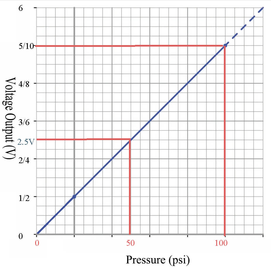
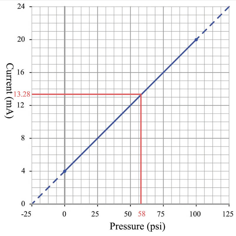
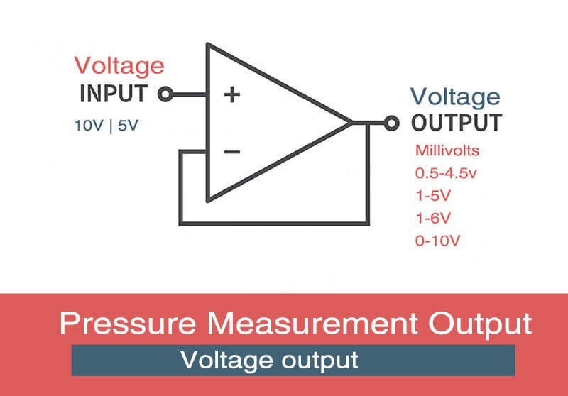
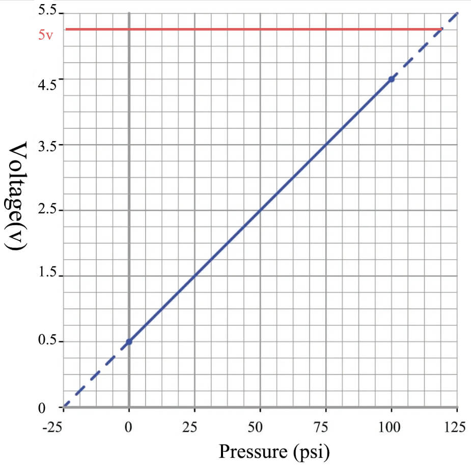
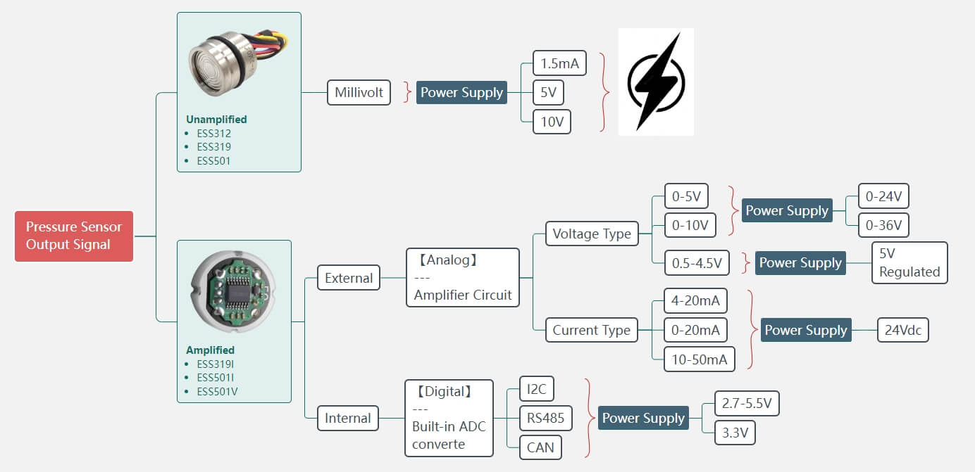
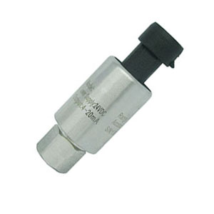
Pressure sensors have a variety of output types. While analog output, such as 0.5-4.5V or 4-20mA, is common and can be suitable for some applications, the RS485 Pressure Sensor has its unique advantages, especially in certain environments and use cases.

In today post, we will discuss the details about RS485 Pressure Sensor, including the highlight feature and drawback, the difference between other similar digital output, also the technical notion when design and use RS485 as pressure sensor output.

What is RS485 digital protocol?

RS-485, also known as TIA/EIA-485, is a standard defining the electrical characteristics of drivers and receivers for use in serial communications systems. It is a common choice for industrial and scientific applications due to its ability to communicate reliably over long distances and in electrically noisy environments.

Here are some key characteristics of the RS-485 protocol

1. Differential Signaling

Unlike protocols that use single-ended signaling (like RS-232), RS-485 uses differential signaling. This means it uses two wires to transmit each signal as a pair of complementary voltages. This makes it more robust against electrical noise and capable of communicating over longer distances (up to approximately 4000 feet or 1200 meters).

2. Multi-Point Communication

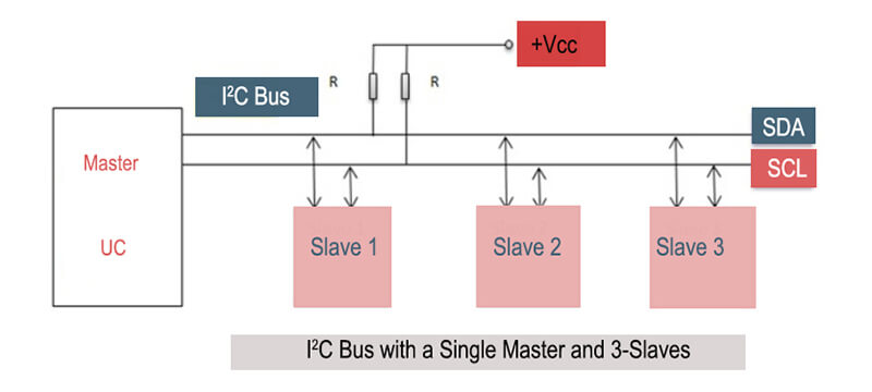
RS-485 supports multiple devices on a single bus (up to 32 without special measures). This makes it suitable for networking devices over a common communication line.

3. Half-Duplex or Full-Duplex

Depending on the setup, RS-485 can be used for half-duplex or full-duplex communication.

  • Half-duplex (using two wires) allows devices to either send or receive data at any one time
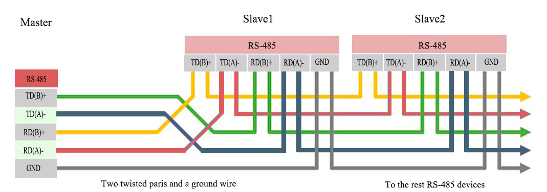
  • Full-duplex (using four wires) allows devices to send and receive data simultaneously.

4. Speed and Distance

RS-485 can operate at speeds up to 10 Mbit/s, or at lower speeds for longer distances.

5. Termination and Biasing

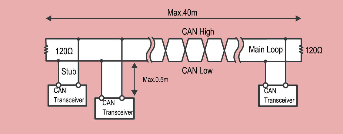
RS485 Pressure Sensor lines often require termination resistors at each end of the bus to prevent signal reflections, and bias resistors to ensure the line defaults to a known state when no drivers are active.

6. Balanced Line Drivers/Receivers

RS-485 uses balanced line drivers and receivers which provide good common-mode noise rejection.

Model of operationDifferential
Number of driver/receivers per line1 driver, 32 receiver
Max cable length4000 feet
Max data rate30 Mbps
Max driver output voltage-7V to 12V
Max driver current in high impedance state (power off)+/- 100uA
Receiver input voltage range-7V to 12V
Receiver input sensitivity+/- 200mV
Driver load impedance54 Ohms
Receiver input resistance>=12 K Ohm

How to differ each other among RS485 and RS232, RS422?

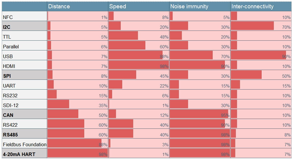
RS-232, RS-422, and RS-485 are all standards for serial communication, but they have key differences that make them suitable for different applications. Here’s a brief comparison:

RS-232

  • RS-232 is a standard for serial binary data signals connecting between a DTE (Data Terminal Equipment) such as a computer terminal, and a DCE (Data Circuit-terminating Equipment).
  • It uses single-ended signals (one signal wire and a common ground), which makes it more susceptible to noise and limits the distance over which data can be transmitted.
  • It supports point-to-point communication only.
  • The maximum cable length is short, typically up to 15 meters.
  • It typically supports data rates up to 20 kbps, but higher rates are possible over short distances.

RS-422

  • RS-422 is a standard for digital data transmission that uses balanced, or differential, signals. That means it uses pairs of wires to transmit data, which improves noise immunity.
  • It supports point-to-point communication only.
  • It can transmit data over much longer distances than RS-232, typically up to 1200 meters.
  • It supports data rates up to 10 Mbps at shorter distances, with lower rates for longer distances.

RS-485

  • RS-485 is similar to RS-422 in that it uses balanced, or differential, signals, which allows for long-distance communication and noise immunity.
  • However, unlike RS-422, RS-485 supports multi-point communication, meaning you can have multiple devices on a single bus.
  • Like RS-422, it can communicate over distances up to 1200 meters and supports data rates up to 10 Mbps at shorter distances.

So, RS-232, RS-422, and RS-485 are serial communication standards used for transmitting data between devices.

RS-232 is the oldest and most widely used, suitable for short-distance communication at lower data rates.

RS-422 is more advanced, allowing for longer distances and higher data rates.

RS-485 is an extension of RS-422, designed for multi-point communication. The choice depends on factors like distance, data rate, and the number of devices involved.

Port nameRS-232RS-422RS-485
Transfer typeFull duplexFull duplexHalf duplex (2-wire)
Full duplex (4-wire)
Max distance15 meters @ 9600 bps1200 meters @ 9600 bps1200 meters @ 9600 bps
Contacts in useTxD, RxD, RTS, CTS, DTR,DSR,DCD, GNDTxA, TxB, RxA, RxB, GNDDataA, DataB, GND
TopologyPoint-to-PointPoint-to-PointMulti-point
Max.No. of connected devices11 (10 devices in receive mode)32 (with repeaters larger, usually up tp 256)

When deciding which standard to use, you need to consider the following and remember that the specific requirements of your application will ultimately determine the best choice:

  • Distance: If you need to transmit data over a long distance, RS-422 or RS-485 would be more suitable than RS-232.
  • Noise Environment: If your system is in a noisy environment, RS-422 or RS-485’s differential signaling can provide better immunity to noise than RS-232.
  • Number of Devices: If you need to connect more than two devices, RS-485’s support for multi-point communication makes it a better choice.
  • Data Rate: If you need to transmit data at a high rate, all three standards could potentially work, but the actual rate will depend on the distance and the specific transceivers you are using.

RS485 Pressure sensor DFR0233 pinout

How do I know whether use RS-422, 2-wire RS-485, or 4-wire RS-485

Choosing between RS-422, 2-wire RS-485, and 4-wire RS485 Pressure Sensor often depends on your specific application requirements. Here are some factors to consider:

RS-422

  • RS-422 is designed for point-to-point communication. It uses differential signaling for noise immunity, and it’s great for long-distance communication (up to 1200m).
  • It uses a 4-wire system: two wires for Tx (transmit) and two for Rx (receive).
  • RS-422 does not support multi-drop or multi-point configurations, meaning only one transmitter and one receiver can communicate on the line.

2-wire RS-485

  • 2-wire RS-485 is used for multi-point It also uses differential signaling, can handle long distances (up to 1200m), and is resistant to noise.
  • It uses a 2-wire system where both wires are used for both sending and receiving data. This means devices take turns communicating (half-duplex).
  • A single 2-wire RS-485 bus can support up to 32 devices.

RS-485 devices with 2 contacts

4-wire RS-485

  • 4-wire RS-485 is also used for multi-point communication and has the same advantages as 2-wire RS-485 in terms of distance and noise immunity.
  • It uses a 4-wire system, with two wires for sending and two for receiving. This allows devices to send and receive data simultaneously (full-duplex).

Like 2-wire RS-485, a single 4-wire RS-485 bus can support up to 32 devices.

RS-485 devices with 4 contacts

To decide which to use, consider:

  • Number of devices: If you only need to connect two devices, RS-422 may be sufficient. If you need to connect more than two devices on a single bus, consider RS-485.
  • Communication type: If your application requires full-duplex communication (simultaneous sending and receiving), consider 4-wire RS-485. For half-duplex communication (devices take turns sending and receiving), 2-wire RS-485 would be suitable.
  • System complexity and cost: RS-422 and 4-wire RS-485 may require more wiring compared to 2-wire RS-485, which could increase system complexity and cost.

At last, you also need to remember to also consider the specifics of your devices and system when making your decision.

For instance, some devices may only support certain protocols, or your system may have physical constraints that affect the feasibility of running additional wires.

Limitation and Risk of RS485 Pressure Sensor

Finally, you’ve made your decision to choose RS485 as the communication protocol, however when using RS-485 communication, there are also several key issues or risks that you need to be considered:

1, Termination Resistor:

Without proper termination, the RS-485 line can suffer from signal reflections that cause communication errors. This is especially important for long lines or high data rates.

To solve this, you should install a termination resistor at both ends of the RS-485 line. The resistor value should match the characteristic impedance of the cable, which is typically around 120 ohms for many types of twisted-pair cable.

2, Biasing

In RS-485 communication, it’s important to ensure that the line defaults to a known state when no drivers are active. Without proper biasing, the line may float and pick up noise, causing errors. To solve this, you should install bias resistors to pull the line to a known state.

3, Ground Potential Difference

If there’s a significant ground potential difference between devices, it can cause large currents to flow in the RS-485 ground line, potentially damaging the devices.

To solve this, you can use isolated RS-485 transceivers or install a ground wire between devices to provide a common reference point and reduce the ground potential difference.

4, Overloading

The RS-485 standard allows for up to 32 unit loads on a single bus. Some devices can be equivalent to more than one unit load, and if too many devices are connected, it can cause communication problems.

To solve this, ensure that the total of unit loads doesn’t exceed 32, or use RS-485 transceivers that are rated for 1/4 (or less) unit load, allowing for more devices on the bus.
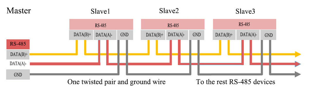
5, Wiring

Incorrect wiring or using the wrong type of cable can cause communication problems. Make sure to use twisted-pair cable for RS-485 communication, and ensure that the A (or +) and B (or -) lines are connected correctly between all devices.

RS 485 PINOUT with M12 Plug

6, ESD and Surge Protection

In some environments, electrostatic discharge (ESD) or electrical surges can be a problem. To solve this, you can use RS-485 transceivers with built-in ESD protection, or install external surge protection devices.

Remember that the specifics of your system will determine which of these issues are most important to consider. Always refer to the datasheets for your devices and plan your system carefully to ensure reliable RS-485 communication.

Which application is best to use RS485 Pressure Sensor?

The RS-485 communication standard is highly versatile and is used in a wide range of applications. It’s particularly suitable for situations where you need to communicate over long distances, in noisy environments, or with multiple devices on a single bus.

Here are a few examples of applications where RS-485 is often used:

1, Industrial Control Systems

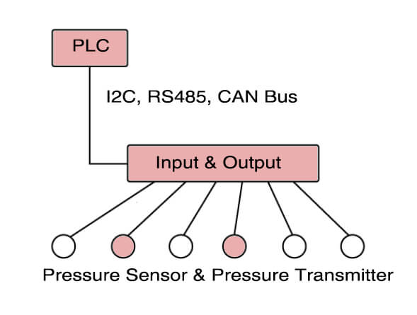
RS-485 is commonly used in industrial environments due to its robustness and noise immunity. It can be used to network various types of machinery and equipment, such as programmable logic controllers (PLCs), sensors, and actuators.

2, Building Automation

In building automation systems, RS-485 is used to connect devices like HVAC systems, lighting controls, security systems, and fire alarm systems. Its ability to handle long cable lengths and communicate with multiple devices makes it a good choice for these applications.

3, Utilities and Energy Systems

RS-485 is used in utilities and energy systems for applications like smart metering, solar panel data transmission, and power grid monitoring. Its robustness and long-distance capabilities are key advantages here.

4, Transportation

In transportation systems, RS-485 is used for applications like traffic signal control, vehicle tracking, and onboard data acquisition.

5, Scientific and Laboratory Equipment

RS-485 can be used to network various types of lab equipment, allowing for centralized data collection and control.

6, POS Systems and Ticketing Machines:

RS-485 is used in point-of-sale systems and ticket vending machines due to its robustness and ability to network multiple devices.

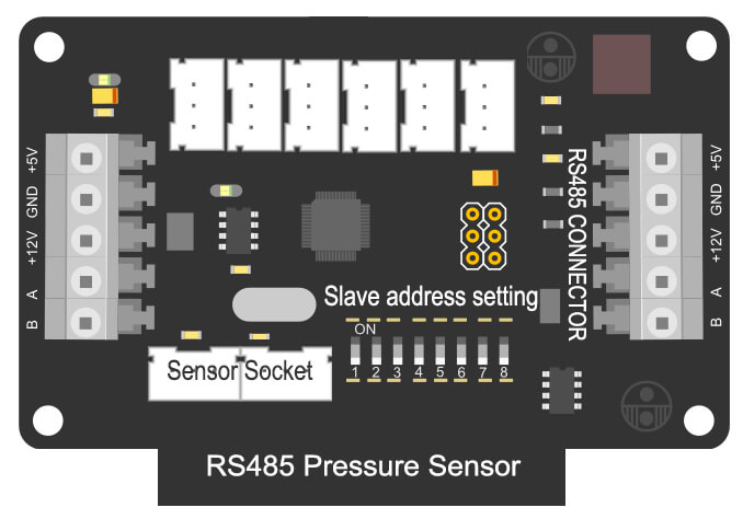
How to design RS485 pressure sensor?

The design of a pressure sensor with RS485 output involves selecting the right sensor, conditioning and converting the sensor’s signal, managing the digital data with a microcontroller, driving the RS485 communication with a suitable transceiver, and choosing appropriate connectors and cabling. Each step should consider the application’s requirements to ensure a reliable, efficient, and effective design.

1. Sensor Selection

Choose a suitable pressure sensor based on the application’s requirements, such as pressure range, accuracy, and environmental conditions. This sensor will produce an analog output proportional to the pressure it measures.

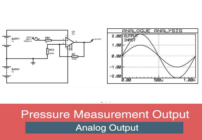
2. Signal Conditioning

The raw signal from the pressure sensor often needs to be conditioned. This typically involves amplification and filtering. An operational amplifier (op-amp) circuit can be used for these tasks.

RS485 Pressure Sensor

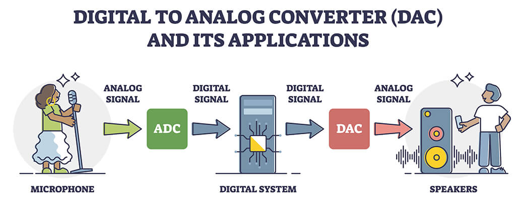
3. Analog-to-Digital Conversion

The conditioned analog signal needs to be converted to a digital format for transmission over RS485. This conversion is performed by an Analog-to-Digital Converter (ADC). The choice of ADC should consider factors like resolution, sampling rate, and power consumption.

ADC-analog to digital-2

4. Microcontroller Integration

A microcontroller is used to manage the ADC and handle the digital signal. It uses the digital data from the ADC, packages it into a suitable format, and prepares it for transmission over RS485. The microcontroller also handles communication protocols and error checking algorithms.

5. RS485 Driver

The digital signal from the microcontroller is sent to an RS485 driver (also known as an RS485 transceiver). This device converts the digital signal into the differential signal required for RS485 communication. The driver must be capable of handling the data rate and network configuration (e.g., half-duplex or full-duplex) required by the design.

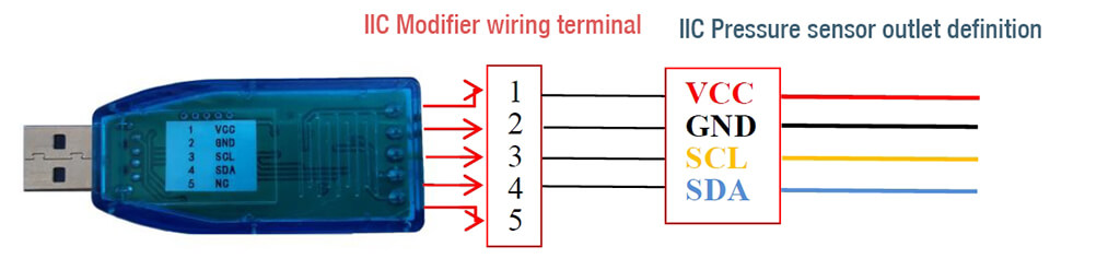
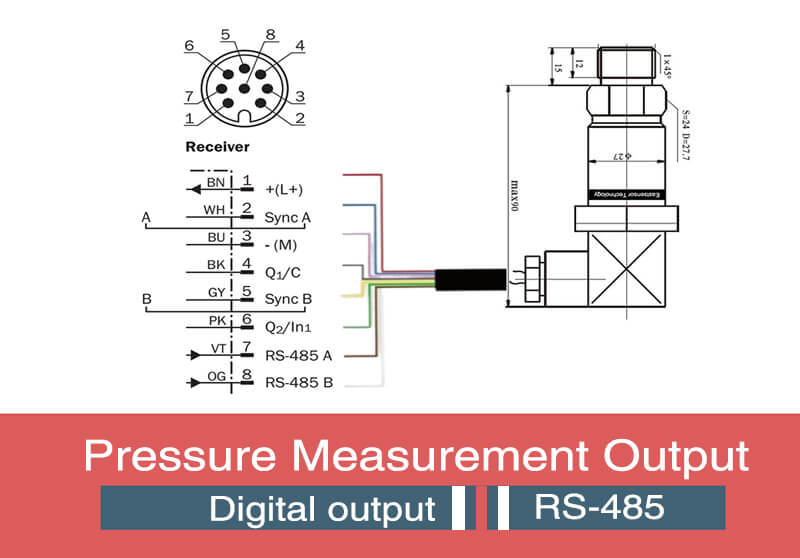
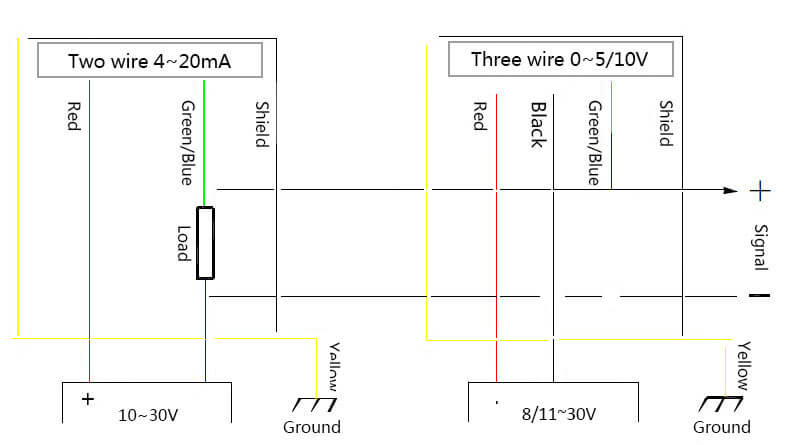
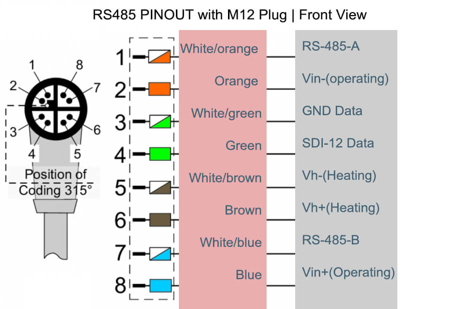
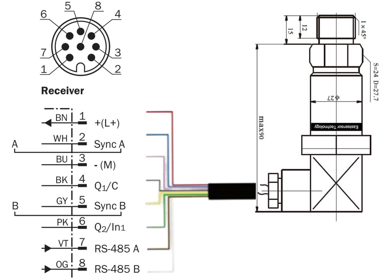
6. Connectors and Cabling

Finally, the appropriate cables and connectors must be chosen to connect the pressure sensor device to the RS485 network. The cabling should be of sufficient quality to handle the data rate and distance required by the application.

What difficulties may have if use RS485 Pressure Sensor?

While RS485 offers many advantages for pressure sensor output, there are challenges that need to be addressed during the system design and implementation:

1. Network Configuration

RS485 supports complex network configurations (like multi-drop networks) that can connect multiple devices on the same communication line. However, setting up such networks can be challenging.

Care must be taken to manage the communication between devices to avoid data collision and to ensure that only one device is transmitting at a time in half-duplex mode.

2. Termination Resistors

For reliable communication, especially over long distances, RS485 networks often require termination resistors at both ends of the communication line. This is to prevent signal reflection that can cause data corruption. Choosing the right value of termination resistor (typically matched to the characteristic impedance of the cable, often 120 Ohms for RS485) is crucial.

3. Ground Potential Differences

In large RS485 networks, significant ground potential differences can occur between devices. This can lead to communication issues or even damage to the RS485 transceivers. Isolated RS485 transceivers or using a common ground reference can help mitigate this issue.

4. Baud Rate vs Cable Length

The achievable data rate (baud rate) in RS485 communication depends on the cable length. For longer cables, the baud rate must be reduced to maintain reliable communication. This trade-off needs to be considered in the system design.

5. Error Handling

Although RS485 supports error detection mechanisms, these need to be correctly implemented in the firmware of the microcontroller. This can add complexity to the firmware design and might require additional computational resources.

6. Cabling and Connectors

Good quality cables and connectors must be used to ensure robust and reliable communication. The cables need to be suitable for differential signaling and should be properly shielded to reduce the effect of electromagnetic interference.

Wrap up

RS485 pressure sensors leverage the RS485 communication protocol to transmit pressure data over long distances, even in noisy environments.

These sensors offer several advantages.

  • They can communicate over distances up to 1200 meters, making them ideal for large installations.
  • They are immune to electrical interference due to differential signaling, ensuring accurate data transmission.
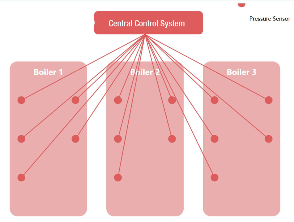
  • RS485 sensors can also be networked, with up to 32 devices on the same line, facilitating centralized data collection.
  • Moreover, as a digital protocol, RS485 integrates easily with digital systems and supports error detection, enhancing system reliability.

However, it also come with certain drawbacks. They require a complex setup involving microcontrollers and RS485 drivers, which can increase development time and cost. Power consumption is generally higher than analog systems due to additional components.

Achievable data rates might be limited, especially over long distances. RS485 networks require careful configuration and termination, and differences in ground potential between devices on large networks can cause issues.

Lastly, RS485 requires twisted pair cables, which are more expensive than simple wires.

Despite these challenges, with proper design and implementation, RS485 can be an effective choice for pressure sensor output.
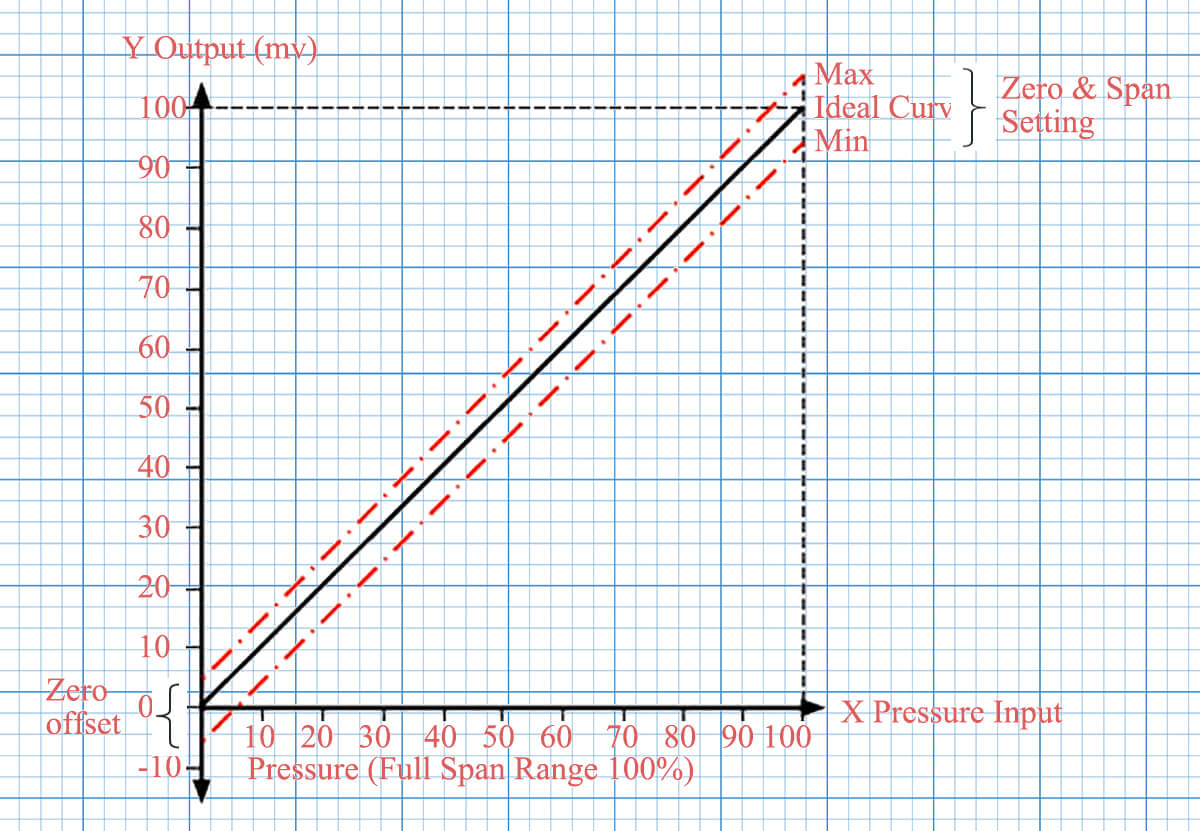
Analog Output Pressure sensor

Analog Output Pressure sensor

What is analog output pressure sensor

An analog output from a pressure sensor is a continuous signal that represents the magnitude of the physical quantity being measured. This signal can take any value within a specified range and varies linearly with the measured quantity.

For example, if the sensor is designed to measure pressures from 0 to 100 psi and has an output range of 0-5V, the analog output changes continuously as the pressure changes, then a pressure of 50 psi would correspond to an output of 2.5V.

There are two common types of analog outputs: voltage and current.

Voltage outputs (e.g., 0-5V, 1-5V, 0.5-4.5V) are typically used in short-distance, low-noise environments.

Current outputs (e.g., 4-20mA) are used where long-distance transmission is required or in environments with high electrical noise because they are less susceptible to signal degradation and interference.

Millivolt output (e.g.,ESS319 and ESS501) which signal not being amplified, always used for miniature and low power devices.

Analog outputs are commonly used in a wide range of applications because of their simplicity, real-time response, and compatibility with a variety of readout and control devices.

ESS319 Silicone Pressure Sensor

ESS501 Ceramic Pressure Sensor

Types of analog output

Analog output signals in pressure sensors are continuous signals that change smoothly over time, directly proportionate to the pressure being measured. The two most common types of analog outputs in pressure sensors are voltage outputs and current outputs.

Voltage Outputs

Voltage output signals typically range from 0-5V, 0-10V, 0.5-4.5V, or 1-5V. The actual range depends on the sensor design and application needs.

A sensor with a 0-5V output, for example, will output 0V when no pressure is applied and 5V when the maximum rated pressure is applied. For any pressure in between, the output voltage scales linearly. So, if the maximum rated pressure of the sensor is 100psi, an output of 2.5V would correspond to a pressure of 50psi.

Some sensors use a 0.5-4.5V output, where outputs below 0.5V or above 4.5V are used to indicate fault conditions.

Voltage Output Pressure Sensor

Check the details about voltage pressure sensor

Current Outputs

Current output signals typically range from 4-20mA. This type of output is less susceptible to electrical noise and is therefore often used in industrial settings or over long transmission distances.

With a 4-20mA sensor, the sensor will output 4mA when no pressure is applied and 20mA when the maximum rated pressure is applied. Like voltage output, the current scales linearly with pressure.

The 4mA lower limit, instead of 0mA, allows the system to distinguish between a zero pressure reading (4mA) and a broken or disconnected sensor (0mA).

4-20mA Pressure Sensor-axis

Check the details about 4-20mA pressure sensor

Millivolt output

The millivolt output typically refers to the raw signal from a sensor element, often a Wheatstone bridge configuration of strain gauges.

The output voltage of this type of sensor is directly proportional to the pressure applied and is usually in the millivolt range, hence the term ‘millivolt output’.

This output is an analog signal because it’s a continuous signal that can take on any value within its range.

There are a few things to note about millivolt output sensors

  • Power supply: usually ratiometric, 1.5mA, 5V, 10V
  • Distance: very short
  • Noise: susceptible to EMI
  • Amplification: need to be amplified


Millivolt Output Pressure Sensor 0-100

Check the details about millivolt pressure sensor

What need to consider when choose analog output pressure sensor

When choosing between voltage and current output signals, you need to consider the following before make decision.

  1. Distance: For longer distances (i.e.100m), choose current output (4-20mA) as it is less susceptible to voltage drops over long distances.
  2. Electrical Noise: If the sensor is in a high noise environment, a current output is a better choice, as it is less affected by electrical noise.
  3. Power Supply: If power supply is limited, a voltage output might be a more suitable choice. These sensors often have lower power requirements than current-output sensors.
  4. Resolution: The resolution is determined by the output range and the pressure range. A larger output range generally provides a higher resolution for the same pressure range.

Always consult the sensor datasheet or the manufacturer to ensure the chosen sensor meets your specific needs.

Below table give the details of highlight feature for different output types.

OutputTransfer DistancePower SupplyHighlight FeaturesMain LimitationsIndustries
mV output± 3m1.5mA | 5V1. Low power consumption
2. Ratiometric output
1. More susceptible to noise interference due to low voltage levels. 
2. Requires more care in system design to preserve signal integrity.
High precision industrial applications, Aerospace, Scientific Research
0.5-4.5V± 10m5V1. Good for fault detection
2. Lower power consumption
3. Widely compatible with devices
Lower voltage range, potentially resulting in lower resolution for the same pressure range.Automotive, Industrial Automation, HVAC
0-5V± 10m5V1. Full use of the 0-5V range for output
2. Good compatibility with many systems
No built-in fault detection like in the 0.5-4.5V or 1-5V sensors.Industrial Automation, Process Control, Automotive
1-5V± 10m5V1. Good for fault detection
2. Providing higher resolution than 0.5-4.5V
1. Slightly higher power consumption than 0.5-4.5V sensors. 
2. Compatibility may be an issue with some systems or devices.
Industrial Control Systems, Process Control, Aerospace
1-6V± 10m6V1. Good for fault detection
2. Providing even higher resolution than 1-5V
1. Highest power consumption among the three types. 
2. Compatibility may be an issue with some systems or devices.
Industrial Control Systems, Process Control, Aerospace
0-10V± 15m10V1. Full use of the 0-10V range for output,
2. Providing even higher resolution than 1-6V 
3. Compatible with systems that require 0-10V inputs
1. Requires higher power supply. 
2. No built-in fault detection.
Industrial Control Systems, Process Control, Aerospace
4-20mA>1000m24V | 36V1. High noise immunity due to current-based transmission.
2. Built-in fault detection (output < 4mA indicates a fault)
3. Transmit data over the same pair of wires 1000-m long
1. Requires a power supply that can provide sufficient voltage and current. 
2. A short circuit can potentially damage the power supply.
Industrial Control Systems, Process Control, Oil and Gas, Water Treatment

Compare analog with digital output

Reason why analog is good

One of the most compelling reasons to choose an analog output pressure sensor relates to its simplicity and direct interpretability.

Analog output sensors provide a continuous signal that varies proportionally with the pressure.

This means the output can be directly and intuitively related to the pressure.

For example, as we mentioned early, if you have a 0-5V analog output sensor designed for a range of 0-100 psi, a reading of 2.5V would directly correspond to a pressure of 50 psi.

You don’t need complex calculations or conversions to understand what the signal means.

Moreover, analog output sensors typically offer robust performance and are less susceptible to total failure compared to digital sensors.

Even if the signal is slightly distorted due to noise or interference, as long as it’s within a tolerable range, the system can still function.

Also, in applications where the signal needs to be sent over long distances or in noisy environments, a 4-20mA current output analog sensor can be a great choice.

Current signals are less susceptible to signal degradation over long distances and to interference compared to voltage signals, making them ideal in industrial environments.

Therefore, the most critical reasons to choose an analog output pressure sensor would be its:

  • Direct interpretability.
  • Robustness, especially in challenging environments.
  • Long transmission distances.

Both highlight features

Both analog and digital outputs have unique benefits, and the choice between the two largely depends on the specific requirements of your application.

Here are the main benefits for each:

Benefits of Analog Output

Simplicity: Analog signals can be easier to understand and interpret, as they provide a continuous signal that directly corresponds to the measurement.

Real-time Output: Analog sensors provide real-time, continuous feedback, which can be critical in certain applications such as process control or monitoring.

No Need for Complex Electronics: Analog sensors can directly interface with simple readout devices, control units, or data loggers without the need for digital-to-analog converters.

Less Susceptible to Total Failure: Analog signals can still provide usable (though degraded) data in the presence of noise or interference, whereas digital signals might become completely unreadable.

Benefits of Digital Output

High Accuracy: Digital sensors can offer very high accuracy and precision, especially for applications requiring detailed, exact measurements.

Immunity to Noise: Digital signals are generally more immune to noise and signal degradation, especially over long distances, compared to analog signals.

Easy Integration with Digital Systems: Digital output sensors can easily interface with modern digital systems, including microcontrollers, digital signal processors, and computers.

Data Storage and Transmission: Digital signals can be stored and transmitted without degradation, making them ideal for applications where data logging is required.

Advanced Features: Digital sensors can include advanced features such as self-calibration, linearization, temperature compensation, and diagnostics that can improve overall system performance.

Wrap up

There are mainly below types of analog outputs:

  • Voltage outputs are used in short-distance, low-noise environments,
  • While current outputs are used for long-distance transmission or in high-noise environments.
  • Millivolt output sensors have a voltage output in the millivolt range and require amplification.

When choosing between voltage and current output, factors to consider include distance, electrical noise, power supply, and resolution.

Analog output sensors offer simplicity, direct interpretability, robustness, and are suitable for long transmission distances.

Digital output sensors offer high accuracy, immunity to noise, easy integration with digital systems, data storage and transmission capabilities, and advanced features.

The choice between analog and digital output depends on specific application requirements.

Voltage Output Pressure Sensor

Voltage Output Pressure Sensor

Contents
2
3

What does voltage output mean for pressure sensor

The voltage output pressure sensor refers to the electrical signal that the sensor produces in response to the pressure it’s measuring. This output is usually a direct current (DC) voltage that varies within a specific range.

The voltage output is proportional to the pressure the sensor is measuring.

For instance,

In a 0-5V output sensor, if the sensor is designed to measure a pressure range of 0-100 psi (pounds per square inch), 0 psi would correspond to an output of 0V and 100 psi would correspond to an output of 5V.

A pressure of 50 psi would then correspond to an output of 2.5V.

Voltage Output Pressure Sensor

The relationship between the pressure and the voltage output is usually linear within the sensor’s specified range. This is often specified as a sensitivity in

  • millivolts per psi (mV/psi)
  • volts per bar (V/bar)

For example,

A sensor with a 0-5V output and a pressure range of 0-100 psi has a sensitivity of 5V/100 psi = 0.05 V/psi. This means that for every psi increase in pressure, the sensor’s output will increase by 0.05 volts.

The advantage of voltage output is that it can be easily interfaced with many types of electronics, including microcontrollers and data acquisition systems, which often accept voltage inputs.

However, voltage signals can be more susceptible to electrical noise and signal loss over long distances compared to current signals (such as 4-20mA), so they are often used in applications where the sensor is not too far from the control system.

How many voltage output types for pressure sensor

Pressure sensors can provide a variety of voltage output types, which are selected based on the specific needs and requirements of a given application.

1. Millivolt (mV) Output

These sensors usually provide a ratiometric output that is proportional to the power supply voltage.

For example, a typical mV output might be 1-100mV for a 1V power supply or 10-1000mV (1V) for a 10V power supply. These sensors are often used in low power applications or when the sensor is part of a Wheatstone bridge configuration.

For example, the low power applications are including:

  • Wearable Devices: Fitness trackers, Smartwatches, Heart rate monitors
  • Internet of Things (IoT) Devices : Environmental monitoring sensors, Smart home devices
  • Remote Sensing Stations: Weather stations, Seismic monitoring systems, Wildlife tracking systems
  • Medical Devices: Glucose meters, Portable ECG monitors, Oxygen saturation monitors
  • Wireless & Battery-Powered Systems: Motion detectors, Smoke detectors, Door/window sensors, Agricultural Sensors

2. 0.5-4.5V Output

These sensors usually provide a ratiometric output relative to the 5v regulated power supply voltage, where 0.5V represents the minimum pressure, and 4.5V represents the maximum pressure.

These are common in automotive and industrial applications due to their ease of integration with many microcontrollers.

0.5-4.5V Pressure Sensor regulated 5v supply

3. 0-5V Output

In these sensors, 0V typically represents the minimum pressure and 5V represents the maximum pressure. The 0-5V output is common and can be easily interfaced with a wide range of electronics.

In many cases, a 0.5-4.5V output pressure sensor can indeed replace a 0-5V output sensor, but you still need to consider a few points before decision make.

4. 0-10V Output

These sensors provide an output where 0V represents the minimum pressure and 10V represents the maximum pressure. They are often used in industrial applications where longer signal transmission distances are required.

5. 1-5V Output

1-5V and 1-6V are two types of voltage output ranges that can be used in pressure sensors. They are similar to the 0.5-4.5V output range in that they include an offset at zero pressure, but the specific values are different.

In a 1-5V output pressure sensor, the output voltage at zero pressure is typically 1V, not 0V. The maximum pressure that the sensor is designed to measure corresponds to an output of 5V.

Just like with a 0.5-4.5V sensor, a 1-5V sensor can provide a clear indication of a fault condition. An output below 1V or above 5V would indicate a problem with the sensor or the system.

6. 1-6V Output

A 1-6V output sensor works in a similar way, but the output at zero pressure is 1V, and the output at maximum pressure is 6V.

As with the other types of output, any voltage below 1V or above 6V would indicate a fault condition.

These types of output ranges are often used in industrial control systems where a clear indication of a fault condition is important. The specific output range used will depend on the requirements of the system and the electronics used to interpret the sensor’s output.

How to decide which voltage output is good for me?

When choosing the voltage output type for a pressure sensor, you’ll need to consider several important factors:

1. Power Supply

The availability and stability of your power supply are key considerations.

If your system primarily operates at 5V, a 0-5V or 0.5-4.5V output sensor might be suitable, if it is regulated 5V, 0.5-4.5v will be the best choice.

However, if you have a 10V supply, a sensor with 0-10V output might be more appropriate.

Pressure Sensor Output signal-2

2. Resolution

The output voltage range impacts the resolution of your measurements.

For example,

A sensor with a 0-10V output range offers twice the resolution of a sensor with a 0-5V range for the same pressure range. This is because the same change in pressure results in a larger voltage change for the 0-10V sensor.

If the pressure range remains the same, a 1-5V sensor would have lower resolution than a 0-5V sensor because the same pressure range is spread over a smaller voltage range.

Check the details of Resolution.

3. Fault Detection

Certain output types have built-in fault detection.

For instance, with a 0.5-4.5V sensor, an output below 0.5V or above 4.5V typically indicates a fault. This can be a useful feature if real-time monitoring of sensor health is critical.

Like the 0.5-4.5V case, 1-5V and 1-6V sensors can also provide fault indication by giving outputs outside of their normal range.

  • 5-4.5v
  • 1-5v
  • 1-6v

4. Compatibility

Ensure the sensor output type is compatible with the input specifications of your data acquisition system or control system. You wouldn’t want to choose a 0-10V sensor if your system can only accept 0-5V inputs.

Similarly, if your system has been designed to interpret 0V as the minimum pressure and 5V as the maximum, it might not interpret the 1-5V or 1-6V ranges correctly.

5. Noise Immunity

Environments with high electrical noise can interfere with voltage signals. In such scenarios, a current output such as 4-20mA might be more suitable due to its superior noise immunity.

Check the details of Noise and EMI

6. Transmission Distance

Voltage signals can degrade over long distances due to resistive losses in the transmission wires. If your sensor is far from your control system, a 4-20mA current output, which remains stable over long distances, might be preferable.

OutputTransfer DistancePower SupplyHighlight FeaturesMain LimitationsIndustries
mV output± 3m1.5mA | 5V1. Low power consumption
2. Ratiometric output
1. More susceptible to noise interference due to low voltage levels. 
2. Requires more care in system design to preserve signal integrity.
High precision industrial applications, Aerospace, Scientific Research
0.5-4.5V± 10m5V1. Good for fault detection
2. Lower power consumption
3. Widely compatible with devices
Lower voltage range, potentially resulting in lower resolution for the same pressure range.Automotive, Industrial Automation, HVAC
0-5V± 10m5V1. Full use of the 0-5V range for output
2. Good compatibility with many systems
No built-in fault detection like in the 0.5-4.5V or 1-5V sensors.Industrial Automation, Process Control, Automotive
1-5V± 10m5V1. Good for fault detection
2. Providing higher resolution than 0.5-4.5V
1. Slightly higher power consumption than 0.5-4.5V sensors. 
2. Compatibility may be an issue with some systems or devices.
Industrial Control Systems, Process Control, Aerospace
1-6V± 10m6V1. Good for fault detection
2. Providing even higher resolution than 1-5V
1. Highest power consumption among the three types. 
2. Compatibility may be an issue with some systems or devices.
Industrial Control Systems, Process Control, Aerospace
0-10V± 15m10V1. Full use of the 0-10V range for output,
2. Providing even higher resolution than 1-6V 
3. Compatible with systems that require 0-10V inputs
1. Requires higher power supply. 
2. No built-in fault detection.
Industrial Control Systems, Process Control, Aerospace
4-20mA>1000m24V | 36V1. High noise immunity due to current-based transmission.
2. Built-in fault detection (output < 4mA indicates a fault)
3. Transmit data over the same pair of wires 1000-m long
1. Requires a power supply that can provide sufficient voltage and current. 
2. A short circuit can potentially damage the power supply.
Industrial Control Systems, Process Control, Oil and Gas, Water Treatment

7. Power Consumption

Power consumption is more directly influenced by the design of the sensor’s internal electronics and the load that the sensor is driving. If the current drawn remains the same, a sensor with 0-10V output would not consume more power than a 0-5V sensor.

Smaller voltage ranges like 0.5-4.5V or 0-5V typically consume less power than larger ranges like 0-10V, which might be advantageous in power-sensitive applications.

8. Safety and Protection

Higher voltage levels may demand more careful handling and protection mechanisms.

A 0-10V sensor may require additional protection circuitry to prevent overvoltage conditions, which can add to the complexity and cost of the system.

Current and Voltage Output

How to balance between 0.5-4.5v and 0-5v?

The most important feature for 0.5-4.5V pressure sensor is that it can indicate faults by outputting a voltage less than 0.5V or greater than 4.5V.

This is a feature not available with a 0-5V sensor.

What is more, both sensors have a 4V-5V span, so they can provide similar resolution if they’re measuring the same pressure range.

So in many industry cases, a 0.5-4.5V output pressure sensor can indeed replace a 0-5V output sensor,

However, there are also cases when a 0.5-4.5V output cannot replace a 0-5V output,

For example:

1. Zero Pressure Reading:

If the system requires the sensor to output 0V for a zero-pressure reading and the device expects a 0V output to indicate zero pressure, a 0.5-4.5V sensor won’t be suitable because its minimum output is 0.5V.

2. System Compatibility:

If the system is designed and calibrated specifically for a 0-5V sensor, replacing it with a 0.5-4.5V sensor might require recalibration or adjustment of the system.

3. Maximum Pressure Reading:

If your system interprets 5V as the maximum pressure reading, a 0.5-4.5V sensor won’t be suitable because its maximum output is 4.5V.

It should be noted that you need to always ensure to check the system requirements and the sensor datasheet, or consult with a technical expert or the sensor manufacturer to ensure compatibility before replacing a sensor.

Industries for voltage output pressure sensor to use

1. Medical Devices

Medical devices such as blood pressure monitors, ventilators, and infusion pumps often use voltage output pressure sensors.

The need for high accuracy and resolution in these devices is paramount, as they directly influence patient health. Many medical devices are battery-powered, making the low power consumption of voltage output sensors an advantage.

For instance, a blood pressure monitor needs to detect very small changes in pressure to accurately measure systolic and diastolic blood pressure.

A voltage output pressure sensor with a high resolution can provide the precision necessary for such measurements.

2. HVAC Systems

In Heating, Ventilation, and Air Conditioning (HVAC) systems, pressure sensors are often used to monitor and control system performance.

Factors like air flow and filter status can be inferred based on pressure measurements. Since these systems are often digitally controlled, the easy interfacing of voltage output sensors to microcontrollers or other digital systems is a key advantage.

For example, a pressure sensor might be used to detect when a filter is becoming clogged (as indicated by an increase in differential pressure across the filter).

A voltage output sensor can provide a direct input to the system controller, enabling it to trigger a filter change alert.

3. Automotive Systems

Automotive systems use pressure sensors in a variety of applications, including tire pressure monitoring, fuel system control, and engine management. These systems often require sensors that can provide high-resolution measurements in a compact, low-power format, making voltage output pressure sensors an excellent choice.

In a tire pressure monitoring system, a small, low-power sensor is needed to fit within the wheel assembly and run on a small battery.

A voltage output sensor can meet these requirements, providing accurate pressure measurements to help ensure optimal tire pressure and vehicle safety.