Millivolt Output Pressure Sensor

Millivolt Output Pressure Sensor

Introduction

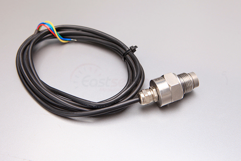
A millivolt (mV) output pressure sensor is a type of sensor that generates an output signal in millivolts, proportional to the pressure it measures. This output is typically a low-level voltage that changes with pressure and is usually derived directly from the sensing element, without any amplification.

Features of Millivolt Output Pressure Sensor

Millivolt output pressure sensors are often used in applications where

  • Power supply voltages are low,
  • Cost is a significant factor,
  • The user has the capability to amplify and condition the signal as needed.

Examples of such applications might include battery-powered devices, portable equipment, and certain types of industrial instrumentation.

Millivolt Output Pressure Sensor 0-100

What are highlight feature of mv output pressure sensor

1. Low-Level Output

Millivolt output sensors typically produce a very low voltage output, often in the range of tens to hundreds of millivolts at full scale pressure.

For example, a common output might be 100mV at full scale pressure.

ESS3 Series Range & Output

RangeOver-pressureOutput/F.SPressure
0-10kpa300%0-57mvG
0-20ka300%0-100mvG/D
0-35ka300%0-70mvG/A/D
0-70ka300%0-67mvG/A/D
0-100ka300%0-75mvG/A/D
0-200ka300%0-75mvG/A/D
0-400ka300%0-68mvG/A/D
0-600ka200%0-110mvG/A/D
0-1000ka200%0-93mvG/A/D
0-1600ka200%0-147mvG/A/D
0-2000ka200%0-65mvG/A/D
0-3500ka200%0-100mvG/A/D
0-7000ka200%0-140mvG/A
0-10Mpa200%200mvG/A
0-25Mpa150%150mvS
0-40Mpa150%230mvS
0-60Mpa150%110mvS
0-100Mpa150%115mvS
The actual millivolt output value may vary a little bit accordingly environment changes

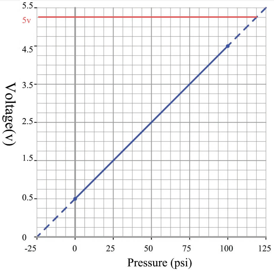
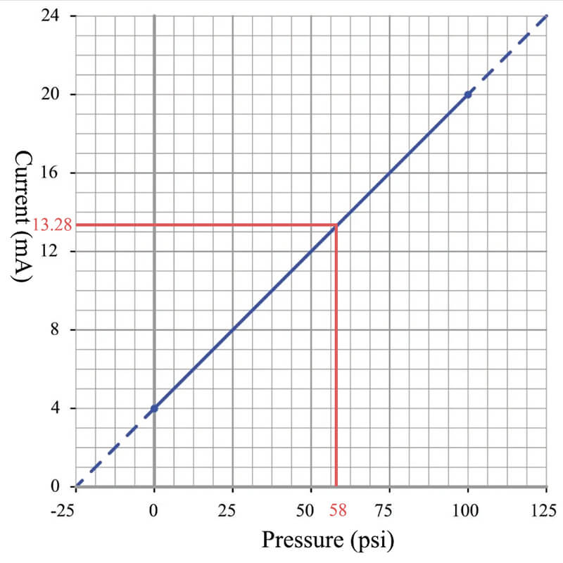
2. Proportional Output

The output of a millivolt sensor is proportional to the pressure it measures.

If the pressure doubles, the output voltage doubles. Conversely, if the pressure is zero, the output voltage is also zero.

3. Power Supply

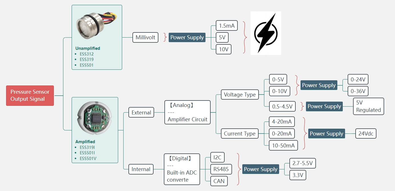
Millivolt output pressure sensors typically operate on a low voltage power supply, often around 5-10V, in Eastsensor, we provide 5V, 10V excitation as voltage and 1.5mA as current. They are sometimes referred to as “ratiometric” because their output signal is often a ratio of the supply voltage.

Pressure Sensor Output signal-2

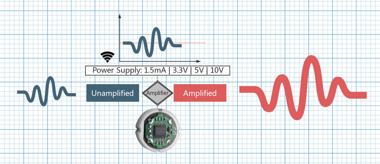
4. Amplification Needed

Because the output signal is so low, it usually needs to be amplified before it can be used. This can be done with an external amplifier circuit or an analog-to-digital converter (ADC) with a built-in amplifier.

ADC-analog to digital

5. Temperature Considerations

The output of millivolt sensors can be affected by temperature changes.

Some sensors include built-in temperature compensation to correct for this, while others may require external compensation.

Pros and Cons of Using Millivolt Output Sensors

Millivolt output sensors, including pressure sensors, have their own set of advantages and disadvantages that make them suitable for some applications and less suitable for others. Here’s a look at some of their pros and cons:

Advantage of mv output pressure sensor

1.Lower Power Consumption:

Millivolt output sensors typically consume less power compared to sensors with amplified outputs, making them suitable for battery-powered or low-power applications.

The most common excitation for mv pressure sensor are

  • 1.5mA
  • 5V
  • 10V

2. Cost-Effective

These sensors are generally less expensive than sensors with built-in amplification, as they have fewer internal components.

3. Flexible Signal Conditioning

The user has the flexibility to design the signal conditioning circuitry (like amplification and filtering) to meet the specific requirements of their application.

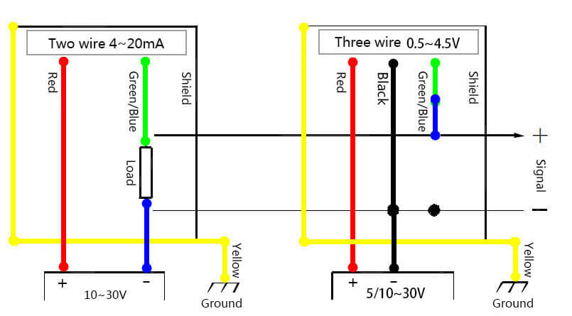
The regular output signal after conditioning are:

4. Direct Sensor Output:

Many types of pressure sensors, such as piezoresistive sensors, generate a millivolt-level signal directly from the sensing element. This simplifies the sensor design and reduces cost.

Disadvantage of mv output pressure sensor

1.Low Signal Level

The output of millivolt sensors is typically very low, which means it can be more susceptible to electrical noise and interference. This could require shielding, filtering, or other noise-reduction techniques.

Check the details: Pressure Sensor Noise & EMI

2. Need for Amplification

The low-level signal usually needs to be amplified before it can be used, which adds complexity and requires additional components in the system design.

3. Voltage Supply Variations

The output of millivolt sensors can be affected by changes in the supply voltage. This may require a stable power supply or additional signal conditioning to correct for supply voltage variations.

4. Temperature Effects

The output of millivolt sensors can be affected by temperature changes, which may require additional components or circuitry for temperature compensation.

Check the details:

The choice to use a millivolt output sensor will depend on the specifics of the application, such as power availability, cost considerations, noise environment, temperature range, and the required signal range.

Application where millivolt output pressure sensor is commonly used

Now let us discuss the specific application where millivolt output pressure sensors are commonly used, it is Battery-Powered Wireless Tire Pressure Monitoring Systems (TPMS) in vehicles.

Tire Pressure Monitoring Systems continuously monitor the air pressure in the tires and alert the driver when the pressure falls below a specified level. This is important because maintaining correct tire pressure helps to ensure the safety and efficiency of the vehicle.

The pressure sensors used in these systems need to be small and consume very little power, as they are located inside the tire and are powered by a small battery. These requirements make millivolt output pressure sensors an excellent choice.

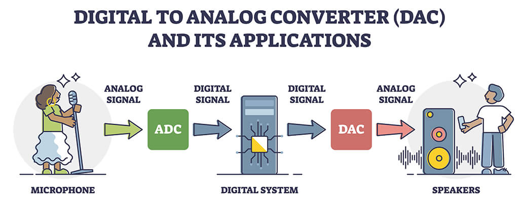
The millivolt signal from the pressure sensor is typically conditioned (amplified and filtered) and then digitized by an analog-to-digital converter (ADC) before being transmitted wirelessly to a receiver/display in the vehicle.

The low power consumption of the millivolt output sensor helps to maximize the battery life of the system.

How does temperature affect the output of millivolt output pressure sensor

Temperature can have a significant effect on the output of millivolt output pressure sensors. This is due to the physical properties of the materials used in the sensor elements and the electronic components.

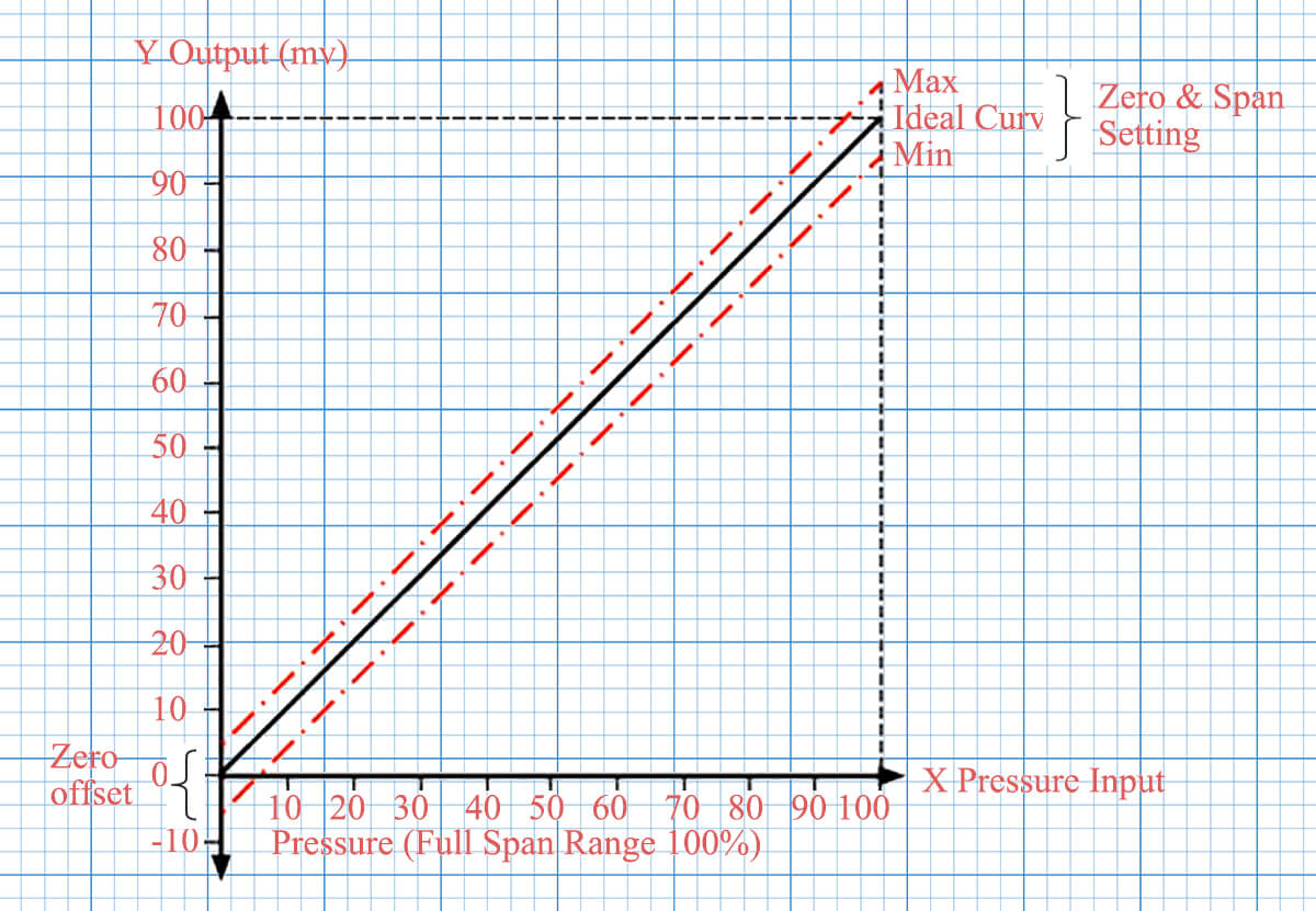
There are two main ways temperature can affect the sensor:

1.Zero Shift or Offset

Changes in temperature can cause a shift in the sensor’s zero point, which is the output of the sensor when no pressure is applied. This is sometimes called “zero drift” or “zero offset.” For instance, if a sensor has a zero point shift of 1mV/°C, and the temperature changes by 10°C, the output of the sensor could shift by 10mV, even without any change in pressure.

2. Span or Sensitivity Shift

Changes in temperature can also affect the sensor’s sensitivity, which is the change in output per unit of pressure change. This is sometimes called “span drift.”

For example, if a sensor has a sensitivity of 100mV/bar and a span shift of 0.1%/°C, a temperature change of 10°C could alter the sensor’s sensitivity by 1%, changing it to 101mV/bar.

These temperature effects can introduce errors into the pressure measurement, especially in applications with large temperature variations.

To manage this, some millivolt output pressure sensors include built-in temperature compensation mechanisms. These typically use additional sensing elements to measure temperature and adjust the pressure reading accordingly.

In other cases, the user may need to provide external temperature compensation. This can be done by measuring the temperature separately and then adjusting the pressure reading based on the known temperature effects of the sensor.

It’s important to account for temperature effects in order to ensure accurate and reliable pressure measurements across the intended temperature range of the application.

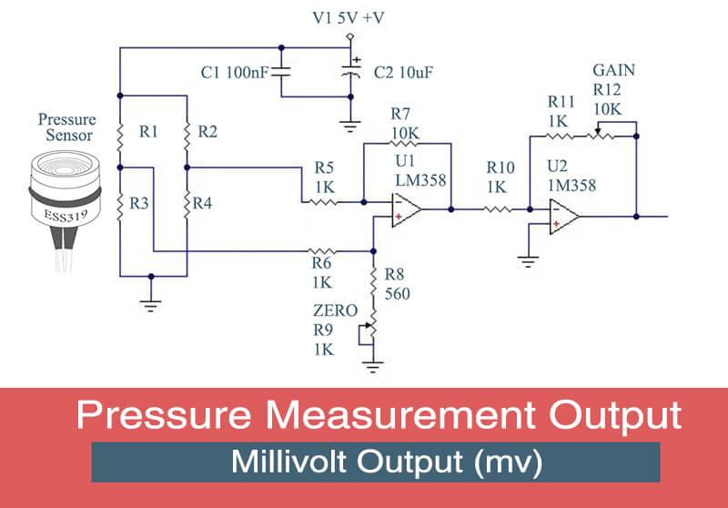
What are some common methods for amplifying the millivolt output pressure sensor

There are several common methods for amplifying the low-level output signal of millivolt output pressure sensors. Here are three of the most commonly used methods:

ES power supply and output (1)

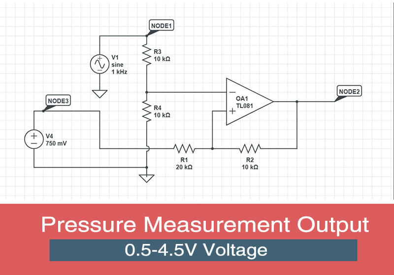
1. Operational Amplifier (Op-Amp):

An operational amplifier is a versatile electronic device that can be used to amplify a low-level signal. In a configuration known as a non-inverting amplifier, the op-amp can amplify the voltage signal from a pressure sensor. The amount of amplification (known as the gain) can be precisely controlled with resistors.

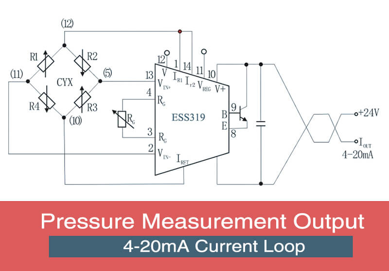
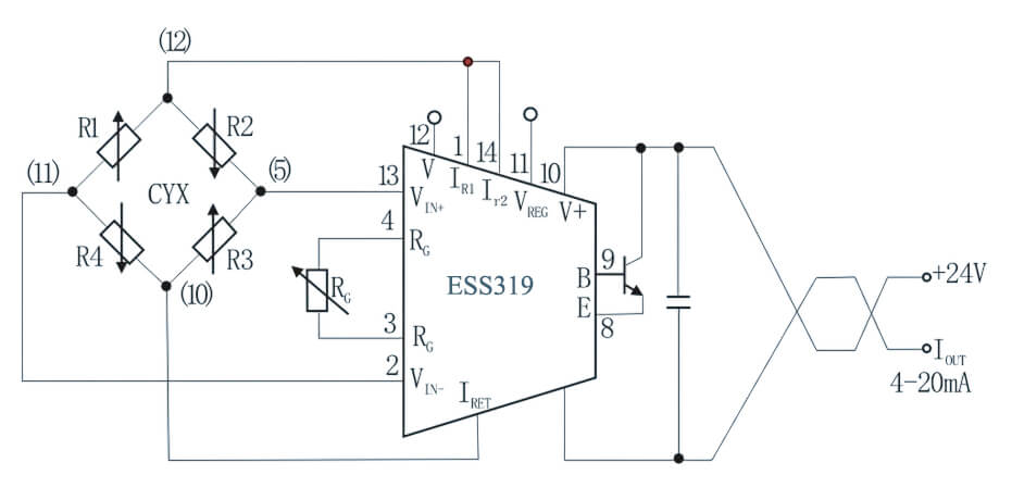
2. Instrumentation Amplifier:

An instrumentation amplifier is a special type of op-amp circuit that is particularly suited for use with sensors. It has high input impedance, low output impedance, high gain, and is designed to reject common-mode noise. It’s often used when long signal wires are present, or the signal is small and needs precise amplification.

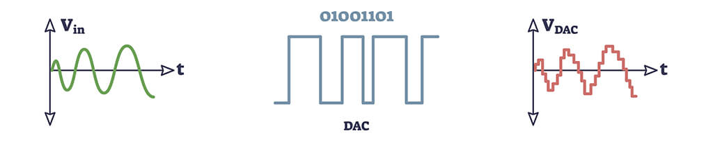
3. Analog-to-Digital Converter with Built-in Amplifier:

Some analog-to-digital converters (ADCs) have built-in programmable gain amplifiers (PGAs). The PGA can amplify the signal before it’s converted to a digital value, increasing the effective resolution of the ADC for low-level signals. This can be a convenient option when the sensor is being interfaced with a microcontroller or other digital system.

Each of these methods has its own advantages and considerations. The choice between them depends on factors such as the specific requirements of the application, the available power supply, the noise environment, and the desired signal resolution. In all cases, care must be taken in designing and implementing the amplifier circuit to ensure that it doesn’t introduce noise or distortion that could affect the accuracy of the pressure measurement.

Click to check details: Millivolt Output Pressure Transducer

0.5-4.5V Pressure Sensor

0.5-4.5V Pressure Sensor

What is 0.5-4.5V Pressure Sensor

A 0.5-4.5V signal output is a common standard for pressure sensors and other types of sensors. This type of output is often referred to as a “ratiometric” voltage output because the output voltage is proportional to the ratio of the measured pressure quantity to the full-scale range of the sensor.

Here’s how it works:

The pressure sensor outputs a voltage of 0.5V when there is no pressure applied (0% of full scale).

This is the “zero” or “offset” voltage.

The output voltage increases linearly with pressure, up to a maximum of 4.5V at full scale (100% of the measured range).

The output voltage is ratiometric to the supply voltage. This means that the output voltage is a certain ratio of the supply voltage, rather than a fixed absolute voltage.

For example, if the supply voltage changes, the sensor’s output voltage will change proportionally.

The advantage of this type of output is that it can be directly interfaced with many types of digital systems, such as microcontrollers, without the need for additional amplification or signal conditioning. It also has a higher signal level compared to millivolt output sensors, which can help to reduce susceptibility to noise and interference.

However, 0.5-4.5V output pressure sensor typically consume less power than 4-20mA current output sensors, which can be a significant advantage in battery-powered or energy-sensitive applications.

Current and 0.5-4.5v Voltage Output connection

On the other hand, it’s important to note that 0.5-4.5V output sensors typically consume more power than millivolt output sensors, and they often require a regulated power supply for accurate measurements.

As with all sensor types, the choice to use a 0.5-4.5V output sensor depends on the specifics of the application.

Why use 0.5-4.5V output instead of 0-5V?

The use of a 0.5-4.5V output instead of a 0-5V output for pressure sensors and other kinds of sensors often comes down to a couple of key reasons:

1. Interfacing with Microcontrollers:

A 0.5-4.5V output is well-suited for interfacing directly with many microcontrollers. The majority of microcontrollers have built-in analog-to-digital converters (ADCs) that accept a 0-5V input.

ADC-analog to digital-2

By using a sensor with a 0.5-4.5V output, you can ensure that the full range of the sensor’s output can be read by the ADC, even if the actual supply voltage is slightly less than 5V due to tolerances or voltage drops.

2. Error and Fault Detection:

In many applications, it’s important to be able to detect when a sensor is not functioning correctly.

If a sensor has a 0-5V output, and the output goes to 0V, it could be due to the sensor measuring the minimum value of the physical quantity (e.g., pressure), or it could be due to a fault in the sensor or the wiring.

By using a 0.5-4.5V output, you can distinguish between these two cases. If the output goes below 0.5V or above 4.5V, it indicates a possible fault.

3. Power Supply Considerations:

In some cases, you might not have a perfectly stable 5V supply.

For instance, if you’re running on battery power, the supply voltage could decrease over time. If a sensor has a 0-5V output, a decrease in the supply voltage could cause the sensor’s output to be clipped at the high end.

With a 0.5-4.5V output, you have some margin to accommodate decreases in the supply voltage.

4. Compatibility with Industrial Standards:

The 0.5-4.5V range is a common standard in industrial applications, so using a sensor with this output range can help ensure compatibility with other equipment.

While a 0.5-4.5V output might seem unusual at first glance, it offers several practical benefits in a variety of applications.

Power supply for 0.5-4.5v output pressure sensor

A pressure sensor with a 0.5-4.5V output typically requires a power supply that is slightly higher than the maximum output voltage. This is because the sensor needs some overhead to generate its output signal, drive its internal electronics, and account for any potential voltage drops in the system.

While exact requirements can vary between different sensor models, a common power supply voltage for these sensors is 5V. This gives the sensor enough overhead to generate its 0.5-4.5V output signal while still allowing for some variation in the supply voltage.

However, some sensors may be designed to operate with a wider range of supply voltages.

For example,

some sensors might be able to operate with a supply voltage anywhere between 5V and 30V. These sensors typically include internal voltage regulators to ensure stable operation regardless of the supply voltage.

A 0.5-4.5V pressure sensor, like many other sensors, requires a regulated power supply for a couple of reasons:

What is and Why 0.5-4.5V Pressure Sensor need regulated power supply

What is regulated power supply

A regulated power supply is a system that provides a constant output voltage regardless of changes in load current or variations in the input voltage. This is achieved through a process called voltage regulation.

0.5-4.5V Pressure Sensor regulated 5v supply

There are two main types of regulated power supplies:

1. Linear Regulated Power Supplies:

These use a voltage regulator circuit to maintain a constant output voltage. The voltage regulator adjusts its resistance based on the load to maintain the desired output. While they are simple and provide low-noise, they can be inefficient, especially when there is a large difference between the input and output voltage, because the excess power (voltage difference multiplied by the current) is dissipated as heat.

2. Switching Regulated Power Supplies:

Also known as switch-mode power supplies (SMPS), these use a switching element (usually a power transistor) that switches on and off rapidly to stabilize the output voltage.

The high frequency on-off cycle is then smoothed with inductors and capacitors to provide a steady DC output. While more complex, they are also more efficient, especially at higher power levels, and can be made compact.

In applications where stability and precision are crucial, such as in the operation of a 0.5-4.5V pressure sensor, a regulated power supply is necessary to ensure that the output voltage accurately correlates with the measured pressure, and is not influenced by fluctuations in the power supply or load.

Why regulated power supply is good for 0.5-4.5V Pressure Sensor

A 0.5-4.5V pressure sensor typically requires a regulated power supply for accurate and reliable operation. This is primarily due to how the sensor’s output voltage is produced and how it corresponds to the sensor’s input (the pressure).

The output of a 0.5-4.5V pressure sensor is a scaled representation of the input pressure, based on the supplied power. If the supplied power fluctuates, the output voltage, which is a proportion of this supply, will also fluctuate.

This means that a variation in the power supply voltage will result in a corresponding variation in the output voltage, which can be misinterpreted as a change in pressure.

For example,

Let’s consider a hypothetical pressure sensor that operates with a 5V power supply and provides an output of 0.5-4.5V depending on the measured pressure.

If the power supply drops to 4.5V, the sensor’s output might also drop proportionally.

A pressure that previously resulted in a 2.5V output might now produce a 2.25V output.

The control system could misinterpret this as a decrease in pressure, when it’s actually a result of the decreased power supply.

Therefore, to ensure the accuracy of the sensor’s output, a stable and regulated power supply is typically required. This ensures that the output voltage accurately represents the measured pressure, rather than any fluctuations in the power supply.

Cos and pros of 0.5-4.5V Pressure Sensor

A 0.5-4.5V pressure sensor has several advantages and drawbacks, depending on the specific application and system requirements.

Pros of 0.5-4.5V Pressure Sensor

1.Fault Detection:

The 0.5-4.5V output allows for built-in fault detection. If the output voltage falls below 0.5V or rises above 4.5V, it indicates a fault or error in the system. This can be crucial in maintaining system safety and reliability.

2. Power Supply Tolerance

The 0.5-4.5V output range provides a buffer against variations in the power supply. If the supply voltage drops slightly, the sensor can still utilize its full output range without clipping at the upper end.

3. Compatibility

The 0.5-4.5V range is a common standard in industrial applications, making these sensors compatible with many systems and devices.

4. Noise Immunity

Compared to sensors providing a millivolt output, a 0.5-4.5V output sensor is less susceptible to electrical noise and interference, leading to more accurate readings.

Cons of 0.5-4.5V Pressure Sensor

1.Reduced Resolution

Since the sensor is not using the full 0-5V range, the resolution is slightly reduced. For applications that require very high precision, this could be a disadvantage.

2. Power Requirements

These sensors typically require a regulated power supply, which can add complexity and cost to the system compared to sensors that can operate with a wider range of supply voltages.

3. Integration Complexity

If the downstream electronics expect a 0-5V signal, additional circuitry may be required to translate the 0.5-4.5V signal to the expected range.

As with any component selection, the choice to use a 0.5-4.5V pressure sensor should be based on a thorough analysis of the system requirements, including factors like power availability, accuracy requirements, environmental conditions, and cost constraints.

How to decide between 0.5-4.5V and 4-20mA output

Deciding between a 0.5-4.5V and a 4-20mA output for a pressure sensor depends on the specific requirements and constraints of your application, when you make decision, here are three key considerations for your reference:

1. Distance and Noise Immunity

For applications where the sensor and the control system are located far apart, a 4-20mA sensor could be more suitable. This is because current signals, unlike voltage signals, do not diminish over long distances.

Furthermore, 4-20mA signals are less susceptible to electrical noise, which could interfere with the signal in electrically noisy environments or over long cable runs.

For example, if you have a sensor located 100 meters away from your control system in an industrial setting with high electrical noise, a 4-20mA sensor would give a more accurate and dependable signal compared to a 0.5-4.5V sensor.

2. Power Supply Considerations

A 0.5-4.5V sensor typically requires a more stable and regulated power supply. If your system has a stable 5V power supply, the 0.5-4.5V sensor could be a good fit.

On the other hand, 4-20mA sensors can operate with a wider range of supply voltages, making them more suitable for systems with variable or unstable power supplies.

For instance,

If you’re working with an off-grid system powered by a solar panel and a battery, where voltage can fluctuate based on solar input and battery charge level, a 4-20mA sensor would be a more reliable choice.

3. System Compatibility and Fault Detection

The control system or data acquisition device’s input requirements also play a crucial role in the decision. If your system is designed to accept a 0.5-4.5V input, a pressure sensor with this output would be more straightforward to implement.

Similarly, if your system is designed for a 4-20mA input, a sensor with this output might be better.

Additionally, both types of sensors can offer built-in fault detection.

  • For a 0.5-4.5V sensor, output falling below 0.5V or rising above 4.5V could indicate a fault.
  • For a 4-20mA sensor, a reading below 4mA or above 20mA could indicate a fault.

For example, in safety-critical applications like a pressure control system in a chemical plant, where early fault detection can prevent potential safety hazards, this built-in fault detection feature can be a significant advantage.

Pressure Sensor Output signal-2

Remember, the choice between a 0.5-4.5V and a 4-20mA pressure sensor should be based on your specific application requirements, including factors like sensor location, power supply stability, system compatibility, and the need for fault detection.

Top industries use 0.5-4.5V Pressure Sensor

0.5-4.5V pressure sensors are widely used in various industries due to their flexibility, ease of integration with many microcontrollers, and relatively low power consumption.

Below I will list some of them, where 0.5-4.5V output is most popular and accepted

1.  Automotive Industry

In the automotive sector, pressure sensors are essential to ensure optimal vehicle performance and safety.

They are used for monitoring:

  • Fuel Pressure
  • Oil Pressure
  • Tire Pressure

2. Industrial Process Control

In systems such as pipelines, tanks, or vessels, maintaining the right pressure is crucial. Pressure sensors help detect overpressure or under-pressure situations, which could lead to inefficiencies or safety risks.

Also, a sudden drop in pressure can indicate a leak, which could be hazardous in industries dealing with chemicals or gases. Pressure sensors provide real-time monitoring to quickly identify and address such issues.

They are used for monitoring:

  • Monitor System Pressure
  • Leak Detection

3. HVAC Systems

In Heating, Ventilation, and Air Conditioning systems, pressure sensors monitor the pressure in ductwork and use this data to control fans and dampers, achieving a balanced and comfortable airflow throughout a building.

An unexpected change in pressure could indicate a problem, such as a blocked filter or a failing component. Early detection allows for prompt maintenance, preventing more significant damage or inefficiency.

In this filed, they are used for monitoring:

  • Manage Airflow
  • Detect Issues

4. Battery operated system

What is more, in certain applications, particularly in the domains of vehicles or battery-operated systems, there arises a necessity for an output signal that can be efficiently operated at low power, thereby ensuring an extended service life.

It is customary for ratiometric signals to be transmitted within the range of 10 to 90 percent of the power supply voltage.

Devices equipped with ratiometric output do not generate an internal reference voltage. Instead, all components function in direct proportion to the prevailing voltage, adhering to the fundamental principle of operating “in ratio.”

By omitting the inclusion of components required for generating the internal reference voltage, the power requirements imposed on the electronics are significantly diminished, thereby contributing to enhanced energy efficiency and overall performance.

In each of these above industries, the use of a 0.5-4.5V pressure sensor provides clear advantages.

4-20mA Pressure Sensor

4-20mA Pressure Sensor

The Role of 4-20mA Pressure Sensor

Current output signals in pressure sensing refer to the method by which a sensor communicates the pressure it’s measuring to other devices. The most common type of current output is 4-20mA Pressure Sensor, a current loop standard in many industries.

4-20mA Current Loop

The 4-20mA current output works on the principle that the current running through the loop is proportional to the pressure being measured by the sensor.

For a given pressure range,

  • 4mA represents the lowest pressure
  • 20mA represents the highest

For example,

A pressure sensor with a range of 0-100 psi (pounds per square inch) outputs 4mA of current at 0 psi and 20mA at 100 psi.

If the sensor is measuring a pressure of 50 psi, halfway between 0 and 100, the output would be 12mA, halfway between 4 and 20mA.

Understanding 4-20mA Current Loop Output Signals in Pressure Sensors

Current output signals, particularly the widespread 4-20mA standard, play a crucial role in pressure sensing. They offer a robust and reliable method of conveying pressure information from the sensing location to a remote reading or control device.

What 4-20mA Pressure Sensor can do?

  • Can be used for hundreds or even thousands of meters long distances
  • Can be installed in environments with high electrical noise
  • Can easily detect the fault
  • Give proportional representation of the pressure
  • Have wide compatibility and easy integration

4-20mA Pressure Sensor pcb circuit-2-eastsensor

1. Data Transmission Over Long Distances

Current output signals can be transmitted over long distances without signal degradation. This is in contrast to voltage signals, which can degrade over long cable runs.

For example, a sensor installed in an industrial plant can send accurate readings to a control room located hundreds of meters away.

Current output signals maintain their integrity over long distances.

The reason for this is that in a 4-20mA current loop, the current is regulated to remain constant across the entire loop, regardless of any changes in resistance along the loop (for example, due to increased cable length or changes in temperature).

This means that a 4-20mA current signal can be reliably transmitted over hundreds, or even thousands, of meters without significant loss of signal quality.

This makes current output signals particularly beneficial in large industrial facilities where the sensor and the monitoring or control equipment may be far apart.

Voltage signals are also more susceptible to interference from external electrical noise, which can additionally degrade the signal over long distances.

For short distances, such as in smaller machinery or consumer electronics, voltage output can be perfectly adequate. However, for longer distances, current output is generally the superior choice due to its greater signal integrity and noise immunity.

2. Noise Immunity

Electrical noise, common in industrial environments, can interfere with signal transmission.

Current output signals are less susceptible to such noise compared to voltage signals. This ensures that the pressure information is accurately conveyed, even in electrically noisy environments.

The primary reason that current signals are less affected by electrical noise compared to voltage signals lies in the very nature of these signals:

2.1 Consistency of Current:

In a 4-20mA current loop, the current is kept constant across the entire loop at any given time. This means that any induced noise would need to significantly alter the current level to affect the signal. This is much harder to achieve than altering a voltage level due to the physical properties of electric currents.

2.2 Voltage Drops and Noise:

Voltage signals are more susceptible to noise because they can be influenced by voltage drops across the line due to resistance, particularly in long cable runs. This is not an issue with current signals, as the current remains constant across the loop, regardless of line resistance.

2.3 Ground Potential Differences:

Voltage signals can be affected by differences in ground potential between different points in the system, which can introduce noise.

Current signals are largely unaffected by this issue.

In practical terms, this means that a pressure sensor using a 4-20mA current output signal can be used in environments with high electrical noise without the fear of the signal being distorted before it reaches the control system or display.

3. Easy Fault Detection

The 4-20mA current range is designed to facilitate fault detection.

A signal below 4mA or above 20mA, or a complete drop to 0mA, indicates a problem.

In a 4-20mA system, the “live zero” at 4mA is a key to fault detection:

3.1 Circuit Integrity:

If the current ever drops to 0mA, it typically indicates a break in the circuit, such as a severed wire or disconnection.

In a voltage signal system, a 0 voltage could either mean a circuit break or a zero measurement, making it harder to distinguish between the two. But in a 4-20mA system, 0mA can only mean a fault in the loop.

3.2 Sensor or Device Failure:

Any current reading below 4mA or above 20mA is also considered a fault condition. If the current falls below 4mA, it could suggest an issue with the sensor or other equipment in the loop, such as power supply problems. If the current goes beyond 20mA, it could indicate an over-range condition or a sensor malfunction.

3.3 Communication Errors:

Variations in the signal that are not consistent with the behavior of the system (for example, erratic fluctuations) could indicate a communication problem, such as noise interference or signal reflection. These can be identified and diagnosed by monitoring the 4-20mA signal.

So, the 4-20mA standard provides a clear ‘window’ for normal operation, and any readings outside of that window inherently indicate a fault, making troubleshooting more straightforward.

This capability is one of the key reasons why the 4-20mA standard is widely used in industrial control systems.

4. Proportional Representation

A key aspect of the proportional representation is that it’s a linear relationship.

This means every increment in pressure corresponds to an equally spaced increment in current. This linear relationship simplifies the interpretation of sensor data, as the output can be easily scaled to the input pressure.

For example

Consider a typical pressure sensor with a 4-20mA current loop output.

The sensor’s pressure range might be from 0 to 100 psi (pounds per square inch).

4-20mA Pressure Sensor-proportion-2

In this scenario,

  • 0 psi corresponds to 4mA output,
  • 100 psi corresponds to 20mA output.

This setup implies that the current output is directly proportional to the pressure sensed.

To understand this further, consider a pressure of 50 psi, which is halfway between 0 and 100 psi. The corresponding current would be halfway between 4mA and 20mA, which is 12mA.

Similarly, a pressure of 58 psi, a quarter more of the way from 0 to 100 psi, would correspond to a current a quarter of the way from 4mA to 20mA.

4-20mA Current Loop Pressure Sensor-proportion-2

In mathematical terms, this proportionality can be expressed as:

Current Output = 4mA + [(Measured Pressure / Full Scale Pressure Range) * 16mA]

Using this equation with a pressure of 58 psi in a 0-100 psi sensor gives:

Current Output = 4mA + [(58psi / 100psi) * 16mA] = 13.28mA

4-20mA Pressure Sensor-axis

This shows how the current output from the sensor is a proportional representation of the pressure: as the pressure changes, the current changes proportionally. This proportionality allows the pressure to be accurately measured and monitored over the 4-20mA current loop.

5. Compatibility and Integration

The 4-20mA standard’s wide acceptance and compatibility make it a versatile choice for pressure sensing applications in a variety of industries. Its ease of integration and strong signal integrity over long distances add to its advantages.

5.1 Compatibility

The 4-20mA standard is recognized and understood globally, and as such, it’s easy to find compatible equipment. Many types of industrial control systems, Programmable Logic Controllers (PLCs), and Human Machine Interfaces (HMIs) readily accept 4-20mA signals. This compatibility extends to a wide variety of industries, including manufacturing, oil and gas, water treatment, and more.

5.2 Integration

Integrating a 4-20mA pressure sensor into a system is relatively straightforward due to the prevalence of this standard. The sensor will typically need a power supply, which is often 24 volts DC, although the exact requirements can vary.

The sensor’s current output can be directly connected to the input of the control system or display device. If the device is designed to accept 4-20mA signals, no further signal conditioning should be required. This simplicity makes integrating 4-20mA sensors into a system relatively easy.

However, it’s important to ensure the sensor is correctly calibrated for the pressure range it’s intended to measure. This usually involves applying known pressures to the sensor and adjusting its output to align with these pressures.

Additionally, some advanced systems allow for digital communication over the 4-20mA loop, such as HART (Highway Addressable Remote Transducer) protocol. This can allow for bidirectional communication with the sensor for configuration or diagnostics, although this requires compatible equipment and adds complexity to the system.

Click to check details: 4-20mA Pressure Transmitter

Why is it must be 4mA instead of 3mA or 2mA and 1mA?

The choice of 4mA as the lower limit for current loop standards, like the 4-20mA used in pressure sensors and other industrial devices, was a carefully considered decision and it serves several purposes.

In essence, the 4mA lower limit is a balance between providing enough power for the sensor, allowing for fault detection, improving noise immunity, and maintaining compatibility with existing systems and practices.

1. Fault Detection

The primary reason for choosing 4mA as the lower limit is for fault detection.

As we previously mentioned, if the current ever falls to 0mA, it’s an indication of a fault condition, such as a break in the loop or a power failure. If the lower limit were set at 0mA, 1mA, 2mA, or 3mA, it would be more difficult to distinguish between a legitimate low reading and a fault condition.

2. Power Supply to the Sensor:

Many 4-20mA devices are 2-wire devices, meaning they derive their power from the current loop itself.

The 4mA lower limit provides enough power for these devices to operate correctly, even when the sensor reading is at its lowest.

A lower baseline current might not provide enough power for the sensor to function properly.

3. Noise Immunity:

Electrical noise is a common issue in industrial environments.

Having a baseline of 4mA instead of a lower value helps the signal stand out above the noise, improving the signal-to-noise ratio and ensuring more reliable communication.

4. Standardization and Compatibility

The 4-20mA standard is widely recognized and accepted in many industries.

This ensures compatibility with a wide variety of equipment and systems. A different baseline current would require a shift in equipment and practices.

Why is it must be 20mA instead of 19mA or 21mA?

The choice of 20mA as the upper limit of the 4-20mA standard is largely based on a balance of practicality and historical convention.

The 20mA upper limit is a compromise between safety, power consumption, signal resolution, and compatibility considerations. It ensures that the current levels remain safe and power-efficient, while still providing enough signal resolution for most applications and maintaining compatibility with standardized equipment and systems.

1. Safety

One major factor is safety.

Currents above 20mA could potentially be harmful in certain conditions, especially in the presence of moisture. By setting the upper limit at 20mA, the standard ensures that the current levels remain within a safe range.

2. Power Consumption

Another consideration is power consumption. The higher the current, the more power is consumed. This becomes particularly important when the sensors are battery-powered or when the system includes many sensors. An upper limit of 20mA provides a good balance between signal resolution and power consumption.

3. Signal Resolution

With a 16mA range (from 4mA to 20mA), it’s possible to get a good signal resolution for most applications. If the upper limit was 19mA or 21mA, the range would be slightly smaller or larger, but the impact on signal resolution would be minimal.

4. Standardization and Compatibility

Above benefits make 4-20mA a widely accepted and recognized current loop standard across industries. A different upper limit would deviate from the standard and could potentially cause compatibility issues with existing equipment and systems.

What are other current loop standards

The 4-20mA current loop is the most widely used current loop standard for industrial pressure sensor applications. However, there are other current loop standards used in different contexts.

Let’s compare the 4-20mA standard to a few of these:

1. 0-20mA Standard

This is another current loop standard, but unlike the 4-20mA standard, it doesn’t provide a baseline current for fault detection. This means that if the current falls to zero, it could either indicate a zero measurement or a fault in the system, making it difficult to distinguish between the two.

2. 10-50mA Standard

Although less common today, the 10-50mA standard was used in older telecommunication systems. The higher current levels made it more suitable for long-distance transmission over copper wires with high resistance.

However, it’s less safe and less energy-efficient than the 4-20mA standard, particularly in hazardous environments.

3. 20mA Loop Standard

Some telegraph systems used a simple on-off current loop standard with a single 20mA current level. The presence or absence of the 20mA current represented a binary signal. This is a very different application from analog sensor data transmission and isn’t directly comparable to the 4-20mA standard.

4. Digital Current Loop Standards

In addition to these analog current loop standards, there are also digital current loop standards, such as the HART protocol. The HART protocol can be superimposed on a 4-20mA signal, allowing digital data to be transmitted along with the analog signal. This can be used for transmitting additional information, such as diagnostic data, from a smart pressure sensor.

In comparison to these other standards, the 4-20mA standard strikes a good balance between safety, energy efficiency, transmission distance, and fault detection capability. Its lower current levels are safer and more energy-efficient for most applications, while still being capable of transmission over long distances. The 4mA baseline current allows for effective fault detection and powers 2-wire devices. These benefits, along with its widespread acceptance, make the 4-20mA standard the preferred choice for many industrial sensor applications.

4-20mA pressure sensor wires connection

Drawbacks of current output signal 4-20mA?

While current output signals, particularly the 4-20mA standard, have many advantages that make them suitable for a variety of applications, they also come with a few limitations:

1.Power Consumption:

Current output signals require a certain amount of power to maintain the current loop. In battery-powered or energy-constrained systems, this could lead to faster depletion of power resources compared to voltage output signals.

2. Complexity and Cost:

The transmitters and receivers compatible with 4-20mA current loops can be more complex and expensive compared to those used with voltage signals. This can lead to higher overall system costs.

3. Limited to Single Sensor per Loop:

Each 4-20mA current loop typically represents the output from a single sensor. If you need to monitor multiple sensors, you’ll need multiple loops, which can add to the system’s complexity and cost.

4. Slow Response Times:

While 4-20mA loops are robust and reliable, they can sometimes have slower response times compared to voltage signals, which can limit their use in applications where rapid response to changes is required.

5. Lack of Bidirectionality:

Traditional 4-20mA systems are unidirectional, meaning they only transmit data in one direction – from the sensor to the control system. They don’t inherently support bidirectional communication, which would allow for things like remote sensor configuration or diagnostics.

Application that 4-20mA current loop pressure sensor can be used for

Current output pressure sensors, particularly those using the 4-20mA standard, find wide use in various industrial and commercial applications due to their robustness, reliability, and the ability to transmit signals over long distances without degradation.

1. Industrial Process Control:

Current output pressure sensors are used to monitor and control processes in industries such as chemical, petrochemical, and power generation. These processes often involve high pressures and temperatures, and the sensors help maintain safe operating conditions.

2. Oil and Gas:

In oil and gas applications, pressure sensors are used for well monitoring, drilling operations, and pipeline management. The 4-20mA standard allows the signals from these sensors to be reliably transmitted over long distances.

3. Aerospace:

Pressure sensors are critical in aircraft systems for altitude determination, engine pressure regulation, and hydraulic system monitoring.

In each of above applications, the key advantage of current output pressure sensors is their ability to provide accurate, reliable measurements even in challenging conditions and over long distances.

The 4-20mA standard used by these pressure sensors also allows for simple and effective fault detection and powers 2-wire devices.

What is more, pressure sensors with 4-20mA current loop output standard, are particularly well suited for use in hazardous areas and intrinsically safe applications.

What do you use for pressure transducer output?

What do you use for pressure transducer output?

Transducer Input / Output

An electrical input, called the excitation voltage, is required to operate a pressure transducer.  This DC excitation can vary from 5-10VDC for unamplified transducers with millivolt output, to 8-36VDC for amplified transducers producing voltage or current output.

Eastsensor offer three electrical output options:

  1. Millivolt (mV)
  2. Volt (VDC)
  3. Current (4-20mA)

Below is a summary of these outputs with their pros and cons.

Millivolt (mV) Output

Pressure transducers with millivolt output are generally the most economical pressure transducers. They are often called “low-level” transducers because they are unamplified and only contain passive electronics necessary to develop and thermally compensate the low electrical output of the Wheatstone bridge.  This also means they tend to be smaller and lighter than voltage or current output transducers.

EST330V is one of Eastsensor Millivolt output product, for details please refer to the article of Why you need Millivolt Output Pressure Transducers? 

The actual output of these instruments is directly proportional, or ratiometric, to the excitation voltage. This means that if the excitation fluctuates, the output will change proportionally. As a result of this dependence on a steady excitation voltage, regulated power supplies are highly recommended.

Because the output signal is so low, a millivolt output transducer tends to be more affected by EMI and should not be located in an electrically noisy environment (hand radios, switch gear, electric motors, etc.). The distances between the transducer and the readout instrument should also be kept relatively short.

Transducers with a mV output signal typically have a better Response Time than most high-level output transducers because there is less electronic circuitry and no isolation of the excitation voltage from the output signal.

The basic passive electronics in these low-level transducers can withstand higher and lower temperatures than the active amplifying circuits used in high-level transducers. As a result, millivolt output pressure transducers are popular for use in high heat (+400°F) and cryogenic (-450°F) applications.

Voltage (VDC) Output Pressure Transducer

Voltage output pressure transducers are amplified and add higher level electronics to the low level passive circuit discussed above. This permits the integration of noise filtering, voltage regulation, excitation-to-output isolation, and advanced signal conditioning circuitry.

The additional components of high level output pressure transducers mean they are typically longer and heavier than low level transducers of the same pressure range.

A voltage output transducer provides a much higher output than a millivolt transducer (normally 0-5VDC) and its output can be isolated or non-isolated from the excitation voltage.  Because the output of this transducer is not a direct function of excitation an unregulated power supply is sufficient, provided that it falls within a specified power range.

In addition, the higher level output of this type of electronic circuit is not as susceptible to electrical noise as millivolt transducers and can be used in many more industrial and aerospace environments where greater levels of EMI are found.

The compensated temperature ranges of these transducers generally extend from a low of -65°F [-54°C], to a high of +250°F [+121°C]. This is the normal maximum operational temperature range for active electronic circuits.

For most of Eastsensor product, they can be made of both voltage and 4-20mA output products, you can find model of  EST330F, EST383, EST370, EST3110

Current (4 – 20 mA) Output Pressure Transducer

This type of high-level pressure transducer is also known as a pressure transmitter. Since a 4-20mA current signal is least affected by electrical noise and resistance in the signal wires, these transducers are best used when the signal must be transmitted long distances.

It is not uncommon to use these transducers in applications where the lead wire might be 1000 feet [305 meters] or more.

The excitation range of a Taber Industries 4-20mA unit is wider (8-36VDC) than that of transducers with voltage output, and elaborate EMI protection electronics are not necessary due to the nature of the current loop signal arrangement.

Because of this, there is less electronic circuitry and the Response Time is on a par with 0-5VDC non-isolated units.

For most of Eastsensor product, they can also be made of 4-20mA output products.

Wrapping Up

Voltage output transducers include integral signal conditioning which provide a much higher output than a millivolt transducer. The output is normally 0-5Vdc or 0-10Vdc. Although model specific, the output of the transducer is not normally a direct function of excitation. This means unregulated power supplies are often sufficient as long as they fall within a specified power range. Because they have a higher level output these transducers are not as susceptible to electrical noise as millivolt transducers and can therefore be used in much more industrial environments.

These types of transducers are also known as pressure transmitters. Since a 4-20mA signal is least affected by electrical noise and resistance in the signal wires, these transducers are best used when the signal must be transmitted long distances. It is not uncommon to use these transducers in applications where the lead wire must be 500 metres or more.

So, in short, you must look at your application to find out which output is the best to choose. For higher temperature applications the mV output should be the first consideration. For industrial environments with potentially unregulated power supplies, the voltage outputs will suffice, and for applications where your signal needs to transmit over long distances then a 4-20mA transmitter is perfect.

Still need help? Contact our offices for further help and advice.

Additional Posts which may be of interest

Why you need Millivolt Output Pressure Transducers?

Why you need Millivolt Output Pressure Transducers?

What is Millivolt Output Pressure Transducer

A Millivolt Output Pressure Transducer is a type of sensor used to measure pressure and convert it into an electrical signal in the form of millivolts (mV).

This type of transducer typically operates on a voltage range of a few millivolts, often in the range of 0-5 mV or 0-10 mV, depending on the specific model.

Like other pressure transducers, the mv output transducer consists of a pressure-sensitive element, such as a diaphragm or strain gauge, that undergoes deformation in response to applied pressure. This deformation causes a change in the electrical resistance of the element, which is then converted into a millivolt output signal proportional to the applied pressure.

Millivolt Output Pressure Transducers are commonly used in various industrial, automotive, and scientific applications where precise pressure measurements are required. The millivolt output signal can be easily interfaced with data acquisition systems, controllers, or other devices for further processing and analysis.

The Highlight of Millivolt Output Pressure Transducer

In current process measuring industry, when you consider applying a transducer to get analog or digital readout, you can’t avoid paying more or less attention on which kind of output is good for you. Normally, there are three: Volt (VDC), Current (4~20mA) and Millivolt (mV).

You can click to find more about the relationship & difference between pressure transmitter and transducer if you don’t have clear understanding on them.

The most millivolt output pressure transducers are passive conditioning electronic signal, which means they are unamplified, no transistor and filters,

In case of that, most active components or EMI environment may easily affect their performance.

Millivolt output pressure transducers enjoy the very short response time and the lowest power consumption when it compare to other types like strain gauge.

Pressure transducers with millivolt output are generally one of the normal kind pressure transducers. They are often called “low-level” transducers because they are not amplified and only contain passive electronics necessary to develop and thermally compensate the low electrical output of the Wheatstone bridge.

This also means they tend to be smaller and lighter than voltage or current output transducers.

EastSensor EST330V and the upcoming models are the type with signal output(s) specified in ‘millivolts per volt’ or mV/V. What does this mean and how can you use this to determine the best electronics to use with these transducers?

As mentioned above, the millivolt output pressure transducers are sometime a passive device – it will not produce a signal unless it receives an external power called excitation.

The FSO of EST330V transducer from 0~100mV (nominally around 30mV@FSO), with 3~10VDC nominal excitation.  This also can be expressed as output of 10mV/V, 100mV FSO with 10VDC excitation, or as an output of 10mV per Volt of excitation.

The Millivolt (mV) Output transducers output can be expected in a directly proportionally way, what that means is the output will vary proportionally if provide a fluctuated excitation power supply. So to maintain stable output, EastSensor highly recommend using the regulated power supply.

Due to the low and weak output signal, it will be vulnerable for millivolt output pressure transducers to resistance the EMI, in this case, the transducers shouldn’t be deployed in some electrical interference or noisy circumstance, such as motors, radios or switch gear etc,

What’s more, we also not recommend to keep a comparatively long distance between the millivolt output pressure transducers and readout device, in another word, the shorter the better.

In spite of the low signal for transducers with millivolt output, we must admit that the millivolt output pressure transducers can perform very good response time when it compare with other output type device, why? Because there is no excitation voltage isolation from output signal, and also the less electronic circuitry also contribute on it.

Let’s sum them up and make it clear of what are the pros and cons if use Millivolt Output Pressure Transducers

ProsCons
EconomicalNeed regulated power supply
Less massEMI Vulnerability
Short response timeShort distance

Wrapping up

Pressure transducers are generally available with three types of electrical output; millivolt, volt and 4-20mA. Transducers with millivolt output are normally the most economical pressure transducer. Millivolt output transducers have below attributes your need keep in mind.

  • They tend to work at higher temperatures than the amplified models.
  • The output of the millivolt pressure transducers are nominally around 30mV@FSO.
  • The actual output is proportional to the input power or excitation.
  • The excitation fluctuates, the output will change also.
  • Regulated power supplies are suggested.
  • It should not be located in an electrically noisy environment.
  • The distances between the transducer and the readout instrument should also be kept relatively short.

Additional Posts which may be of interest