Knowledge about Flush Diaphragm Pressure Transmitter

Knowledge about Flush Diaphragm Pressure Transmitter

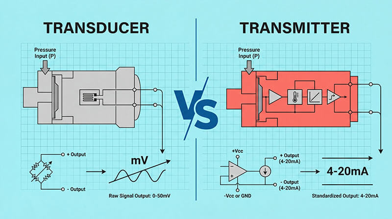
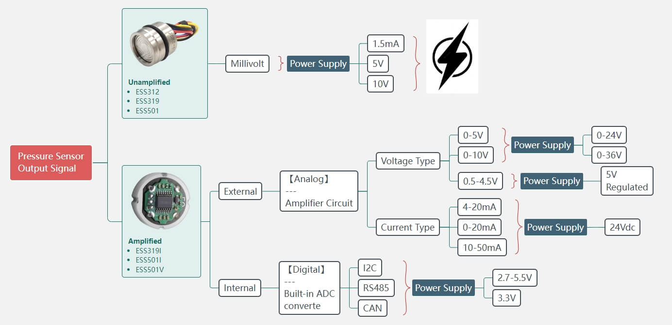
The Flush Diaphragm Pressure Transmitter or transducer can do the same job which other conventional thread connection product can do,  such as convert the applied pressure into an output signal of 4~20mA @ F.S pressure.

However, Flush Diaphragm Pressure Transmitter is also designed to be installed in a series of hazardous situation and is ideal for use in food, beverage sanitary, medical process and industrial applications where the media is either viscous, contains particulates or solids, which may probably cause the clog or foul.

What is Flush Diaphragm Pressure Transmitter?

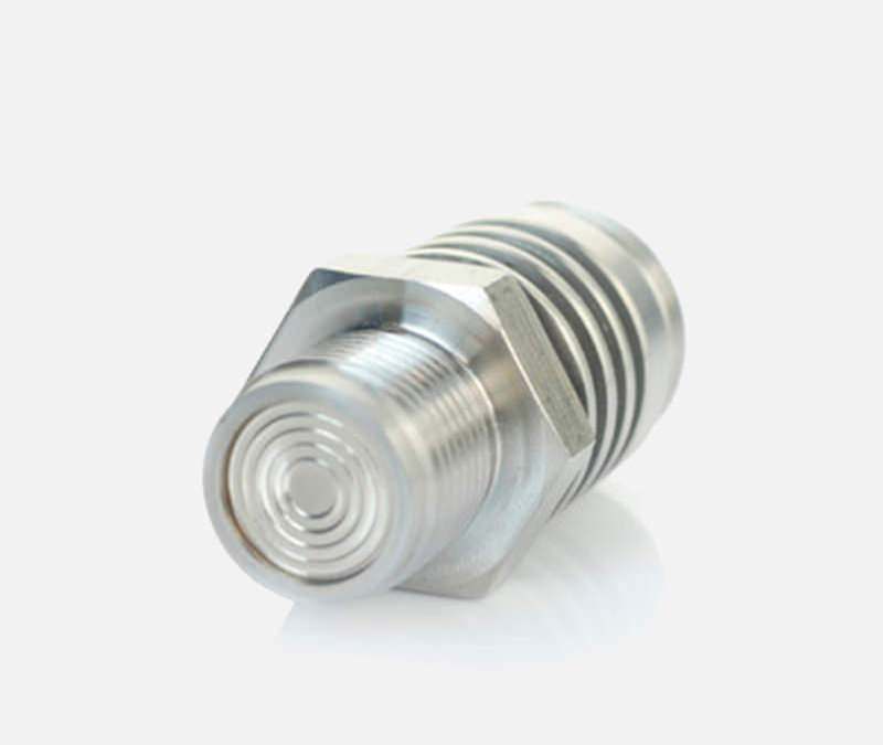
The definition can come to many ways but the commonsense recognize that a Flush Diaphragm Pressure Transmitter is the one with flat surface at the end of the sensor, beyond the process threads and can be deployed in conjunction with viscous fluid or media that may clog a standard process connection or may be otherwise liable to block a standard inlet port as the diaphragm of flush type is open/flush mounted with no cavity.

A Simple Experiment

Let’s grab an egg and place it the palm of your hand, with the pointed end of the egg directed toward your fingers. Close your hand around the egg and squeeze. If you’re doing it properly, your fingers will be pressing down on the pointed end of the egg, and the rounded end will be settled in your palm.

You can squeeze as hard as you can and the egg won’t break. That’s because you’re applying even pressure where the egg is strongest. The eggshell is designed to withstand that kind of abuse. However, if you hit any part of the egg on any surface, it will crack.

A pressure sensor diaphragm is like an eggshell. It can withstand incredible pressure when it is applied evenly across the entire surface. However, putting pressure on a single area or point of the diaphragm will cause problems.

That’s because the diaphragm is very thin – a few thousandths of an inch. It’s actually quite impressive that such a thin sheet of metal can withstand high pressure – tens of thousands of pounds per square inch.

But when an object focuses pressure on a small area or point, the thin diaphragm will be damaged and the sensor may need to be recalibrated or replaced.

The Diaphragm

With most process connections, we can recess the thin diaphragm to protect it from contact with anything other than the process media. However, flush mount diaphragms remove that protection. Instead, the diaphragm is the flat surface at the end of the sensor, beyond the process threads.

The flush mount exists primarily for two major benefits:

  1. There is no recess that can become fouled or clogged.
  2. The sensor can measure flush to the pipe or vessel wall, reducing resistance and maintaining flow.

For the right application, these pros outweigh the cons of having an exposed diaphragm that must be handled carefully. You must keep anything from touching the sensor’s diaphragm except for the process media.

How Torque Affects Flush Mount Diaphragm?

It’s admitted that the torque applied during the installation or mounting process can significantly affect the performance and accuracy of flush mount diaphragm pressure sensors. Here’s how torque affects flush mount diaphragm sensors:

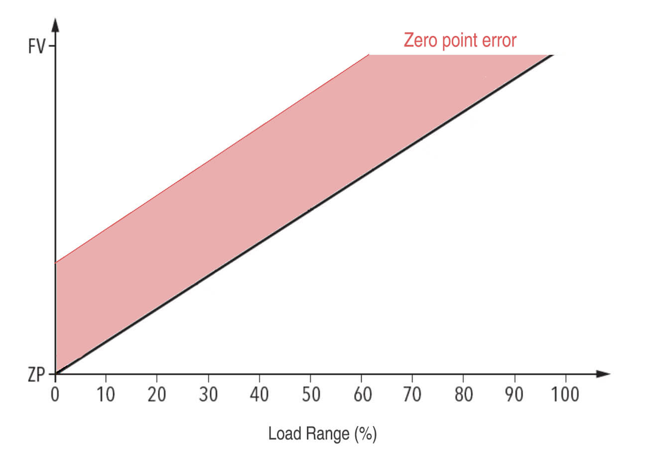
Diaphragm Deformation

The diaphragm is the sensing element in a flush mount pressure sensor, and it is designed to deflect or deform in response to applied pressure. When excessive torque is applied during the mounting process, it can cause mechanical stress and deformation of the diaphragm, even before any pressure is applied. This pre-stressed condition can lead to inaccurate pressure readings and potentially shift the sensor’s zero point.

Stress Concentration

Flush mount diaphragm sensors are typically designed with a thin, flexible diaphragm that is flush with the sensor body. When torque is applied unevenly or excessively during installation, it can create localized stress concentrations on the diaphragm, leading to non-uniform deformation and potential diaphragm failure or fatigue over time.

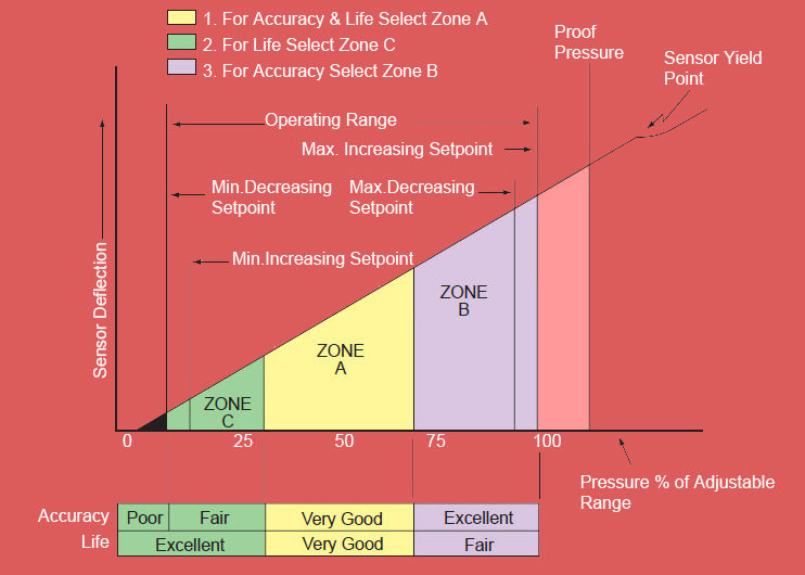
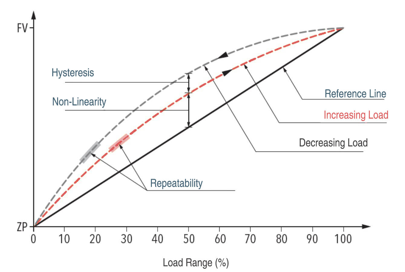
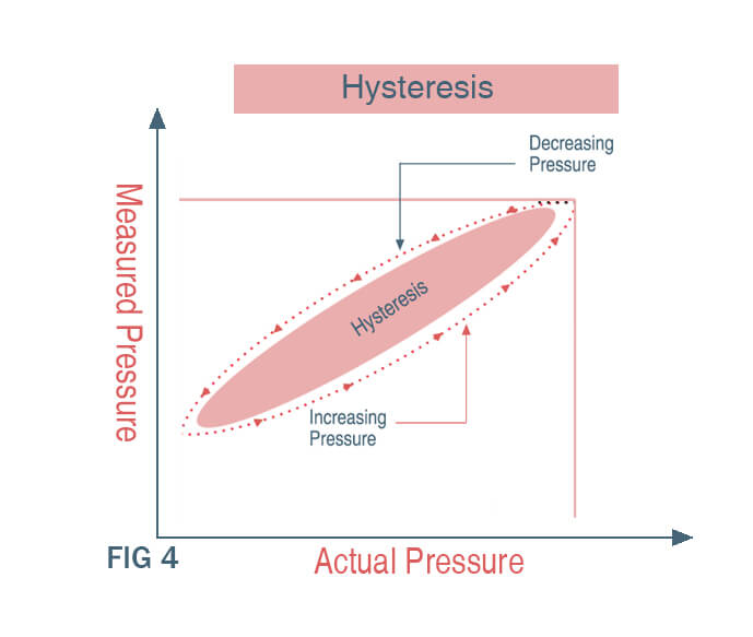
Hysteresis and Non-linearity

Excessive torque can introduce hysteresis and non-linearity in the sensor’s response. Hysteresis refers to the phenomenon where the sensor output differs depending on whether the pressure is increasing or decreasing, while non-linearity means that the sensor’s output is not proportional to the applied pressure across the entire measurement range. These effects can compromise the sensor’s accuracy and repeatability.

Hysteresis Pressure Sensor-eastsensor

Sensitivity Shift

The sensitivity of a flush mount diaphragm sensor, which is the ratio of the output signal to the applied pressure, can be affected by excessive torque. The mechanical stress induced by torque can alter the diaphragm’s deflection characteristics, leading to a shift in the sensor’s sensitivity, which can cause measurement errors.

To mitigate the effects of torque on flush mount diaphragm pressure sensors, manufacturers typically provide installation guidelines and recommended torque values. These guidelines are based on the specific sensor design, materials, and intended application. Following these recommendations is crucial to ensure accurate and reliable pressure measurements.

Additionally, some flush mount diaphragm sensors are designed with torque-insensitive features, such as isolation rings or reinforced diaphragm structures, to minimize the impact of torque during installation. These design features help to decouple the diaphragm from the mounting stresses, enhancing the sensor’s performance and accuracy.

You might be thinking that these sensors sound like they can’t hack it in the real world. They certainly can and do with regularity. They simply require careful handling and installation.

Again, the pros outweigh the cons in the right applications. It’s simply the nature of exposing the sensing elements of a transducer designed to be responsive to small changes in pressure.

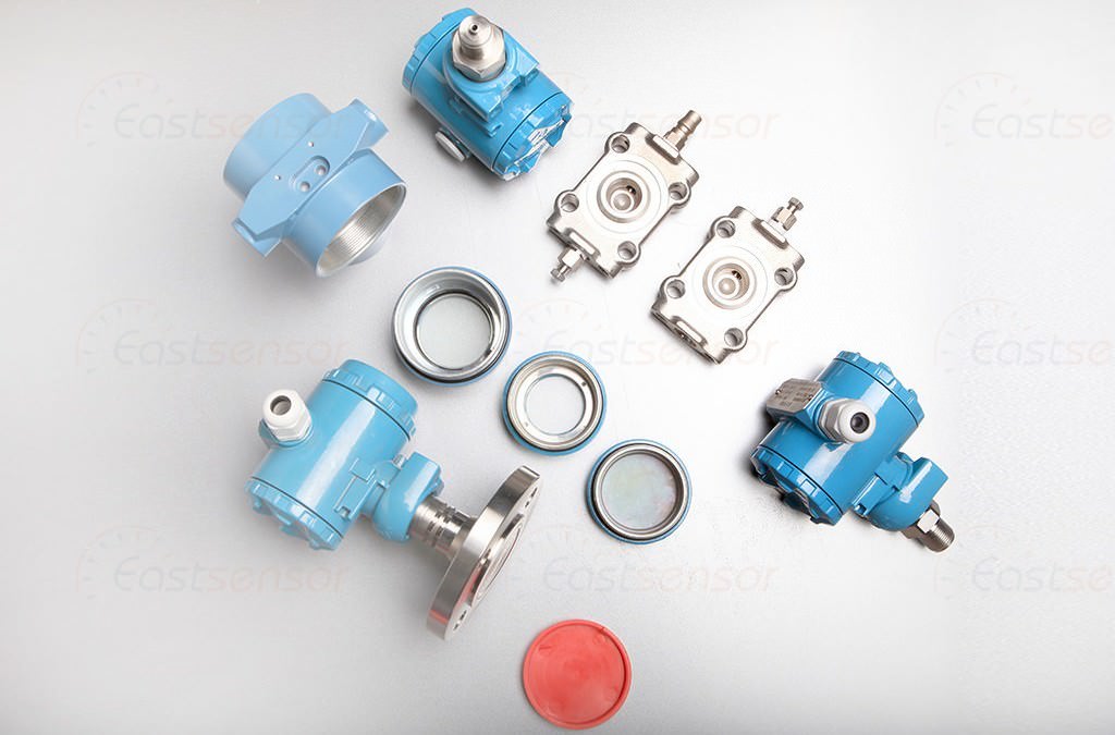
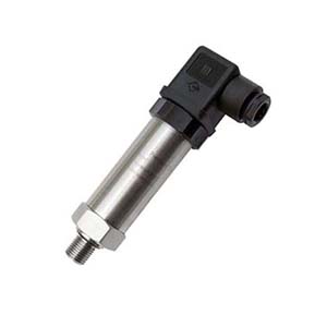
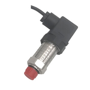
Highlight Features of EST330F

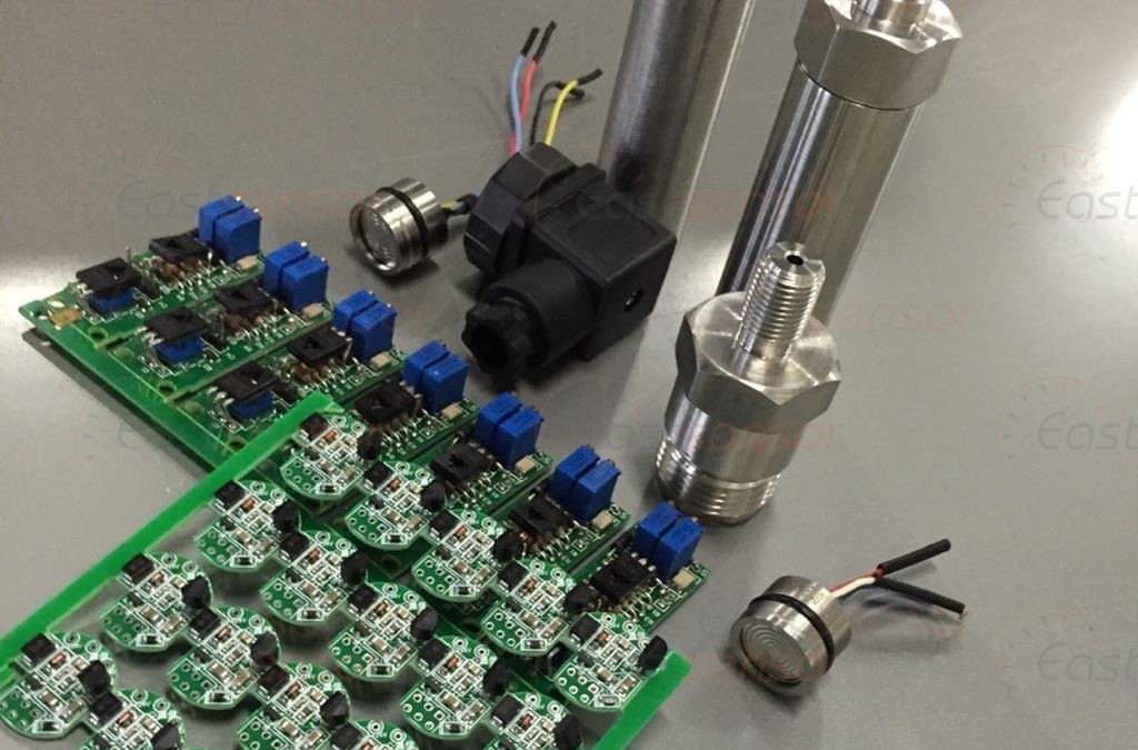
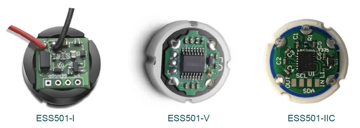
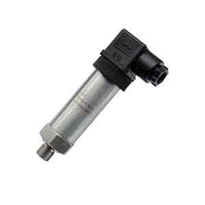
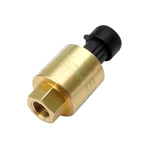
In terms of different situation, Eastsensor produce two kinds of Flush Diaphragm Pressure Transmitter,

  1. The normal type flush diaphragm
  2. The Tri-clamp mounting open face flush diaphragm

Both of them are made ruggedly by SS316L and can be deployed in critical process filed to eliminate any cavity that could form a clog.


EST330F Features goes below

  • Unique flush stainless steel diaphragm eliminates any cavity that could form a clog
  • SS316-gthick diaphragm provides higher overpressure and spike protection
  • Available ranges up to 500 psi
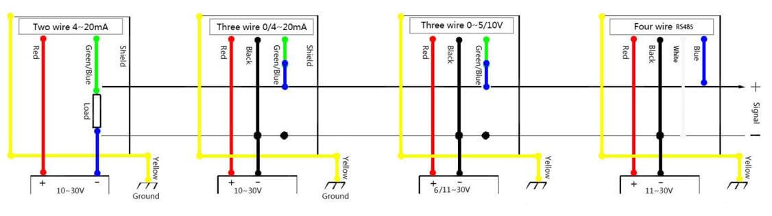
  • Wide range of mechanical and electrical connections
  • ±0.50% accuracy
  • Working temperature up to 150 ℃ (customized)
  • IP65 with HSM/DIN43650 and IP68 with cable connection
  • 1 year Warranty
  • OEM available


What is The Difference between Pressure Transducer and Pressure Transmitter?

What is The Difference between Pressure Transducer and Pressure Transmitter?

More and more people tend to ask what the difference between pressure transducer and pressure transmitter is and what the difference between pressure sensor and pressure transducer is as well. Actually, in EastSensor, our engineers make comprehensive sturdy and consultant then come up with below points to help customers, no matter within or not the measurement instrument filed to have a better understanding among their meaning.

As a matter of fact, the exact definition of these terms are usually interchanged from case to case, but we’d admit that they have general definition as below

Pressure Sensor

A millivolt output signal generally. Millivolt (mV) output signal (also a general term for all pressure types); a device that measures pressure. The millivolt output signal can typically be used ten (10) to (20) feet away from the electronics without significant signal loss.

The signal is proportional to the supply. A 5VDC supply with a 10mV/V output signal produces a 0-50mV output signal. Older technologies such as bonded foil strain gage or thin film technology produce 2-3mV/V (millivolts per volt), whereas MEMS technology can produce 20mV/V reliably.

Millivolt output signals give the design engineer the flexibility to condition the output signal as their system needs it and can reduce package size and cost.

Millivolt Output Pressure Sensor 0-100

Pressure Transducer

An amplified voltage output typically. Transducers are voltage-output devices that can be used with simple signal conditioning but are more sensitive to electromagnetic interference.

The electrical resistance of the connecting cable can cause significant errors if the cable is long. They require three or four connecting wires to supply power and deliver the output signal.

Click to find more details about Why you need Millivolt Output Pressure Transducer?

Pressure Sensor Output signal-2

Pressure Transmitter

Always output 4~20mA signalTransmitters are current-output devices and may have two or three wires. Where two wires are used to both receive power and transmit an output signal, significant cost savings can be made where long cables are needed.

They are frequently scaled to vary from 4 mA to 20 mA as the pressure varies from minimum to maximum. Thus the on-board electronics has to be capable of operating with a maximum current drain of less than 4 mA.

Being ‘current driven’, the in-built circuitry controls the voltage across the transmitters’ two terminals to ensure that the appropriate pressure-proportional current is maintained irrespective of line resistance up to a specified limit.

Thus these devices are very suitable for use with long cables and are much less susceptible to electromagnetic interference than voltage-output transducers. Sometimes called current loop or serial devices, additional displays at different locations can easily be included in the loop without degrading the output signal. Such devices normally suffer no significant degradation of signal output with distance.

4-20mA Pressure Sensor-proportion

Digital output transmitters normally contain a microprocessor which converts measured pressure values into digital codes which are transmitted to a remote receiver, or ‘host’, via wires, optical fibres or radio. There are a number of standard systems available, such as Fieldbus (IEC 1158) and HART, the latter having the facility to operate in combination with the more traditional 4 mA to 20 mA current-output systems.

Beyond supplying pressure values, digital transmission can include diagnostic information, status and alarms and can also facilitate remote reconfiguration of transmitters.

Once the difference can be described to the definition of signal output, the question can be set. Below is a general guideline on such terms and some advantage and disadvantage.

The Difference Between Pressure Transducer and Pressure Transmitter

Pressure Transducer: 

High level voltage or frequency output signal including 0.5 to 4.5V ratiometric (output signal is proportional to the supply), 1-5V and 1-6kHz.

These output signals should be used within twenty (20) feet of the electronics. Voltage output signals can offer low current consumption for remote battery operated equipment. Supply voltages are typically from 8-28VDC, except for the 0.5-4.5V output, which requires a 5VDC regulated supply.

Older voltage output signals, such as 0-5V, do not have a “live zero” where there is signal when the sensor is at zero pressure. The risk is that the system does not know the difference between a failed sensor with no output and zero pressure.

0.5-4.5V Pressure Sensor regulated 5v supply

Pressure Transmitter: 

Current output signal, i.e. 4-20mA (4 to 20mA), the current, rather than the voltage, is measured on the device, rather than the voltage; EastSensor pressure transmitters also have many types of two wire devices (red for supply, black for the ground). 4-20mA pressure transmitters offer good electrical noise immunity (EMI/RFI), and will need a power supply of 8-28VDC.

Because the signal is producing current, it can consume more battery life if operating at full pressure.

Pressure Transducers are available with a variety of voltage output options.

With advances in controllers that receive the transducer signal, there is more flexibility in the marketplace. There are minor differences between many of the output options on the market place. While some developed to maintain competitive advantages via customized products, others have solid reasoning.

The outputs reviewed here are all powered by a minimum of 10VDC (0-10V and 1-10V outputs need 12VDC). A 0.5-4.5V ratiometric output signal is traditionally powered by a 5VDC regulated supply, yet other variations are possible. In a similar way, millivolt output signals have their own unique features and benefits. The following is a brief introduction to amplified voltage pressure transducers.

The Difference Between Pressure Transducer and Pressure Transmitter 3 wire and 4 wire

Zero based output

Traditional pressure transducer outputs include 0-5V and 0-10V signals. Popularized in Europe, zero based output signal produce no output signal at zero pressure in a standard gauge pressure transducer.

Transducers are offered in three wire and four wire configurations with zero based output signals. The advantage of the 0-10V signal is that it has twice the span as the 0-5V. The main disadvantage to any zero-based output signal is that there is no signal with zero pressure.

If the transducer has a cut wire, broken sensing element, or electronics that received an over-voltage, the sensor will produce no signal, thus no way to know of a problem. If we assume that the pressure transducer is measuring water pressure, it will produce a 0V signal when there is no pressure in the line.

Voltage Output Pressure Sensor

When pressure is sensed, it will signal the pump to act. Since the sensor at 0V is the same in fault conditions and at no pressure, there is no way to distinguish between the two. The pump would not know to run, and could cause a flooding condition.

Voltage at zero pressure

There are many variations and custom options for pressure transducers with an output signal at 0 PSI. For example, EastSensor offers 1-3V, 1-5V (for Automotive Industry), and 0.5-4.5V. The 1-5V output signal is most popular in the industry. There is the safety feature of having a 1 volt output signal at zero pressure and a 4 volt span for pressure measurement. 1-3V and 1-5V output signals are popular among engineers who prefer a voltage span similar to the zero based outputs above, but with the signal at zero pressure. The 0.5-4.5V output signal is somewhat unique.

For remote telemetry applications, current consumption is a common factor. Because lithium-ion batteries or solar panels create power in remote oil fields and on construction site equipment, having a low power supply voltage and low current consumption extend the service life of the pressure transducer.

The 0.5V 0PSI signal gives enough indication that the transducer is working. The span to 4.5V gives enough resolution to accurately measure the pressure or level

10 practices need to considerate before choosing pressure transducer

10 practices need to considerate before choosing pressure transducer

How to select pressure transducer for your applications

Currently, many pressure sensors are designed to work with extremely hard situation such as the most corrosive liquid media or hostile properties materials, or in some case to undertake the very easy pressure measuring projects.

It is not easy to select a correct model pressure sensor for correct job requirement, the sensor’s attributes have mostly decide whether a specific pressure sensor is suitable for a particular application, and also the environment it’s being specified for, the task it’s being asked to perform should also be taken into consideration.

You may make a questions list as below before finding a way to select proper pressure sensor to address customers’ specific requirements:

  1. What the application for the sensor is?
  2. Then, you’ll need to ask some of these basic questions, such as, how extreme are the temperatures or corrosive nature of the media being measured?
  3. Is the environment a vibration challenge?
  4. What is the pressure range that needs to be measured in psi, bar, inches of water, etc.?
  5. How much time are you willing to devote to the integration of the sensor, or must it be ready to implement and forget?
  6. What is the pressure type (gauge, absolute, differential)?
  7. How accurate does the pressure measurement need to be? And, just as important, what are the size and price constraints?

You don’t need to answer above questions one-by-one, but below is a general guide to illustrate in which specific aspects you should pay attention before selecting a appropriate pressure transmitter.

Pressure range

To decide the pressure range on the site where the pressure transmitter will be installed will significantly influence the result of selection process. We strongly recommend choosing a pressure range that is a little more than the actual use including pulsation, transient, spike and other abrupt behavior.

If the pressure range is pretty lower than the situation really needs will result in damage to pressure transmitter or transducer, especially in case of voltage bursting if overloading; on the other hand, if the pressure range is rather high than the application actually require, may also cause lower accuracy.

For example, let’s say your nominal operating pressure is 100 psi, with occasional pulsations of ±10 psi and potential transient spikes up to 125 psi. In this case, you might choose a pressure range of 0-150 psi or 0-200 psi, depending on the desired safety margin.

FIGURE Selection of adjustable range for electromechanical pressure switches

So firstly make it clear that what the anticipated pressure spike will be and choose a appropriate high level than that should be a smart way. An additional margin such as 20%~30% is recommended.

Measuring units

To a large extent, the measuring units have been determined by the manufactures before delivery to the market, when receive the pressure transmitter or transducer, the user’s may custom the measuring units within the pre-calibrated range which fixed by supplier.

Eastsensor can provide customers many kind of pressure unit when perform the measuring process, meanwhile, in each model’s specification/data sheet, we have clearly illustrated what exact relationship exist among different measuring units.

  • 1MPa=10bar
  • 1bar=14.5psi
  • 1 Inches of water=3.613 X 10⁻² psi
  • 1 Feet of water= 4.335 X 10⁻¹ psi
  • 1 Inches of mercury= 4.912 X 10⁻¹ psi
  • 1 Millimeters of mercury=1.934 X 10⁻² psi
  • 1 Kilograms/sq. centimeter= 14.22 psi
  • 1 kilopascal= 1.45 X 10⁻¹ psi
  • 1psi=6.8965kPa
  • 1kgf/cm2=1atm
  • 1atm=98kPa

All above units can be easily calculated by the tool of: Pressure Unit Converter 

Gauge, sealed gauge, absolute, differential pressure

At Eastsensor, we offer gauge, vacuum, compound, sealed gage, absolute and differential pressure transducers and pressure transmitters.

relationship and difference among gauge pressure, absolute pressure, differential pressure

Gauge pressure means the pressure measurement are calibrated to the atmospheric pressure locally; we named it as gage type pressure transmitter (psig)

If the devices have been measured the pressure which is less than the ambient pressure, they are vacuum type transmitter (psiv), the compound transducer means a transducer can measure both positive and negative pressure.

When it comes to measure the standard atmospheric pressure at sea levels of 1 bar (14.5psi), and the process situation is in the moistest or most humid properties media, the sealed gage transmitter will be used to conduct the job.

The absolute transducer (psia) can measure pressure relative to a vacuum (zero pressure).

The differential transducer (psid) has an output that is the difference between the pressures applied to its two pressure ports.

Accuracy

FSO on behalf of the full scale output and the accuracy always be presented as the percentage of error to the FSO which also means the algebraic difference between end points.

In another situation, accuracy always had been denoted as percentage of the error to output.

Pressure Sensor Accuracy-and-precision

We’ve admitted that in many cases the static error band the accuracy are always interchanged, but in fact they are not the same.

While the terms “accuracy” and “static error band” are frequently interchanged, they are not the same.

Many factors can contribute to transducers accuracy. Actually, the term “error” is preferred for specifications and other specific descriptions of transducer performance.

Pressure Measurement Errors

The static error band is, however, a good measure of the accuracy that can be expected at constant temperature. The static error band consists of the three following components:

Above static error band can be eliminated by means of root sum square.

Pressure Sensor Hysteresis Linearity Repeatability

A critical factor which contributes the most part of the error in measuring process is thermal effect, it is generally expressed in % per degree, even sometime this is not 100% exactly what it is.

During the pressure measuring process, even a very tiny percentage error per degree can result in very huge problem when checked over the whole expected range.

Thermal effect contributes the largest error in measuring process; Eastsensor guarantee that each of our product thermal effects has been strictly tested and compensated over a certain temperature range.

The compensated temperature range is usually smaller than the operating temperature range, and the thermal sensitivity shift is usually expressed as a percentage of output.

Output signal

We can categorize transducers by their output to low and high level types.

Low-level transducers usually have only passive devices (strain gages and resistors) in their electrical circuits. Thus they are typically more rugged and are able to operate over a wider temperature range. Signal conditioning is external. The highest accuracy over the broadest environmental conditions can be provided with low-level transducers. A typical low-level output is 3 mV/V.

High-level transducers have internal electronic circuits to condition the excitation or supply voltages and the signal. They are easy to install because most of the signal conditioning is already provided. Some typical high-level outputs are 0-5 VDC, 0-10 VDC, 1-5VDC, and 4-20 mA. Most of Eastsensor’s press products are such types.

Pressure Sensor Output signal-2

Zero Pressure Output

The transmitter’s signal output at zero pressure means zero balance, in most cases, zero balance should be zero Volts however, many transmitter have the ability of offsetting output at zero balance, especially if the negative outputs or zero have been outside the parameters range of monitoring computer or recording device.

The offset voltages includes, typically, output of 1~5Vdc OR 2.5~7.5Vdc.

Another normal types of offset output is 4~20mA.

Pressure Sensor Zero point error-2

Pressure Transducer Electrical Connection

Why you select such type of pressure transducer instead of another is mostly depend on the availability of power supplies and the interface of pressure transducer, of course some time the end user’s knowledge on specific type also make influence.

2, 3 or 4-wire electrical connection types can be used when the pressure transducer with high-level outputs.

Regular wires connection types

The pressure transducer, power supply and readout are all connected in series of 2-wire if the users adopt 4~20mA current loop type.

3-wire circuit can return both the excitation and signal commonly, only because 3-wire circuit have the zero balance elevated, that the output signal may vary from between 1~5Vdc or 2.5~7.5Vdc.

Sometime the pressure transducer can output zero pressure in case of the device have internal negative voltage source.

4-wire circuits may have different return connected for both excitation and signal; the output signal is different with and separated from excitation return. Most significant, in 4-wire electrical connection of pressure transducer, the single lines and power supply cannot be tipped at the same point.

Measuring Media Properties

It is critical to know what kind of material type the sensor is made from. Chemical compatibility from the sensor materials that come in contact with wetted materials, can contribute a significant factor in the lifetime of sensor.

More and more measuring media have the properties of corrosion especially when deployed in the harsh environment. In Eastsensor, we adopt 316L stainless steel, ceramic, and sometime titanium alloy as diaphragms which can resistive to many media.

What’s more, we also use thick-film ceramic pressure sensing diaphragms in extreme harsh situation. For some metals also have the ability to provide good corrosion resistive against gas or fluid. Finally, how to decide if a kind of pressure transducer is suitable for a measuring media should never be neglected by users.

ESS501I ESS501V ESS501IIC ceramic pressure sensor-eastsensor

Pressure Connection

There are various ways to seal a pressure sensor to the area that needs to be measured. The type of application generally dictates which type of fitting is needed.

In the United States, a tapered thread (NPT) is used for most common applications. A NPT connection seals by the tapered thread making a connection as it is threaded into the fitting.

However, this type of connection still needs a type of sealant, such as Teflon tape, to keep the connection air/water tight. NPT connections are not rated for pressure over 15,000 PSI and typically not used on applications over 10,000 PSI.

SAE fittings are a straight thread that uses a gasket to produce a seal. SAE fittings are generally used for higher-pressure applications, but are not limited to them.

BSPP threads, also known as G threads, are a straight thread typically used in Europe but are seen in the Unites States. Similarly to SAE fittings, BSPP/G threads are straight threads that use a gasket to seal the connection. BSPP/G threads can be used in general applications as well as for higher pressure.

For sanitary applications, a Tri-Clamp mount can be used. Tri-Clamp fittings have a gasket between the mounting area and the sensor, but do not require any threads. This fitting is sealed by using a special clamp around the circular connection. This type of connections allows for easy removal due to cleaning processes.

Pressure Sensor Process Connection

Find more details about different process connection threads at 

There are many other types of process connections available; all having the proper seal for various applications.

Measuring environment

Gage pressure transducer always tend to expose their internal components to corrosive environment when measure the pressure relative to the local atmospheric, so the sealed gage or absolute types should be considered as the better choice if comes to the corrosive and humid environment.

In some cases that gage pressure transducer is required, a compact no holes housing with vented cable can be a good choice.

On top of above EMI and RFI should also be taking into consideration, Eastsensor engineers are glad to be with you for any technical issues when selecting a prosperous pressure transducer.