Pressure Sensor Temperature Drift

Pressure Sensor Temperature Drift

Introduction

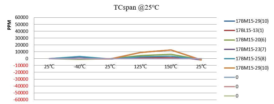
Temperature drift refers to the change in sensor output due to fluctuations in the ambient temperature.

It’s usually expressed in parts per million (ppm) per degree Celsius (°C).

For example, a sensor with a temperature drift of 50 ppm/°C would change its output by 0.005% for each degree Celsius change in ambient temperature.

This drift is primarily influenced by the materials used in the sensor construction, as they expand or contract with temperature changes, causing shifts in the sensor’s performance.

When evaluating the performance of pressure sensors, it’s crucial to consider temperature drift.

Varied temperature conditions can significantly impact the accuracy and reliability of the sensor readings. If a sensor has a high-temperature drift, it might give accurate readings at room temperature but deviate significantly in hotter or colder environments.

A minor deviation can lead to significant errors in critical applications such as medical devices, automotive systems, or industrial controls.

For instance, in a hydraulic pressure control system, a drift of just 1% could result in a pressure error of several hundred psi, potentially causing system failure.

Temperature drift = (Output at high temp – Output at calibration temp)/(Output at calibration temp)

For example, a sensor may exhibit +0.2% output change at 100°C compared to the calibration temperature of 20°C. This means the temperature drift is +0.2%.

Temperature drift can impact important performance parameters like:

ParameterEffect of Increased Temperature Drift
1AccuracyDecreased accuracy over time
2SensitivitySensitivity may change over temperature
3Response TimeSlower response due to material expansion
4HysteresisIncreased uncertainty due to residual stress
5Non-linearityMore non-linear output with wider temperatures
6Long-term StabilityLess stable measurements over years
7RepeatabilityWorse repeatability of measurements

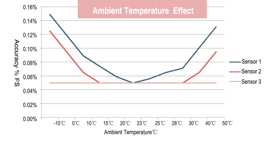
Temperature Drift and its Influence on Accuracy

The most common type of pressure sensor is the piezoresistive sensor that uses piezoresistors to detect pressure changes.

The piezoresistors are usually made of silicon strain gauges that change their electrical resistance when subjected to pressure.

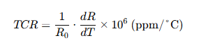
As the temperature changes, the resistance of the piezoresistors also changes due to silicon’s temperature coefficient of resistance (TCR). The TCR of silicon is around 2,800-3,000 ppm/°C, meaning the resistance changes by 2,800-3,000 parts per million for every 1°C change in temperature.

Pressure Sensor Hysteresis -ESS01

This change in piezo resistor resistance due to temperature causes an offset error in the sensor’s output – it makes the sensor think there is a pressure change when there is none. This is the temperature drift of the sensor.

For example,

Let’s say a sensor has a sensitivity of 2 mV/V/bar. At 25°C, the sensor outputs 0 mV at 0 bar pressure.

Now if the temperature increases to 50°C, the piezoresistors’ resistances will change due to their TCR.

This resistance change may cause the sensor’s output to increase by 20 mV, making it look like there is 10 bar (20 mV / 2 mV/V/bar) of pressure even though there is no actual pressure change.

This is a 10 bar offset error due to temperature drift.

Temperature Effects on Pressure Sensor-1

Ways to reduce this drift include temperature compensation circuits, thermal isolation of piezo resistors, using different materials for piezoresistors with lower TCR, and performing temperature calibration of the sensor.

With the proper compensation techniques, high-end pressure sensors can achieve very low-temperature drift of just ±0.05% of full scale output (FSO) over the operating temperature range.

But in many applications, a drift of ±0.1% to ±0.5% FSO is more typical.

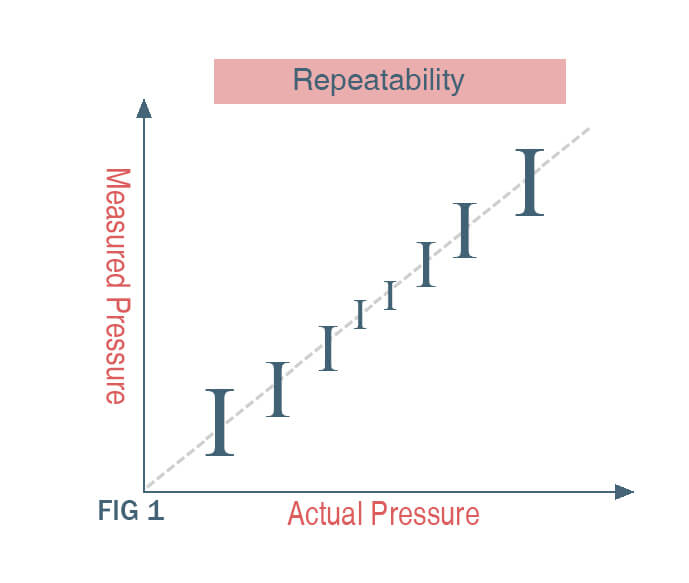
Temperature Drift and Repeatability: An Interconnected Relationship

Repeatability refers to the sensor’s ability to measure the same pressure value consistently when the same pressure is applied multiple times. Temperature drift can negatively impact repeatability in pressure sensors.

FIG 1 Repeatability Pressure Sensor-eastsensor

As explained in my previous answer, temperature changes cause the piezoresistors in piezoresistive pressure sensors to change resistance due to their temperature coefficient of resistance (TCR).

This resistance change manifests as an offset error in the sensor’s output, making it appear that there is a pressure change when there is none.

This offset error due to temperature drift will be different each time the sensor temperature changes, even if the actual pressure remains the same.

This means the sensor will report a different pressure value each time, reducing its repeatability.

The relationship between temperature drift and repeatability can be summarized as:

  • Higher temperature drift leads to lower repeatability
  • Lower temperature drift results in higher repeatability

To quantify this, we can define:

  • Temperature drift = ∆P/∆T (Change in pressure reading per degree temperature change)
  • Repeatability = ±∆P (Pressure reading variation at constant pressure)

We can see that temperature drift ∆P/∆T directly impacts the repeatability variation ∆P. The higher the temperature drift, the larger the pressure variation and the lower the repeatability.

Some technical specifications to look for regarding temperature drift and repeatability are:

  • Total temperature drift: Specified as % of full-scale output (%FSO) over the operating temperature range
  • Repeatability: Specified as %FSO at constant pressure and temperature
  • Temperature coefficient of resistance (TCR) of piezoresistive material: Indicates how much resistance changes with temperature.

Temperature drift causes offset errors that vary each time the sensor heats up or cools down, limiting its ability to report the same pressure consistently and reducing repeatability.

Managing temperature drift through various techniques can therefore improve a pressure sensor’s repeatability.

Hysteresis and the Role of Temperature Drift

Temperature drift will cause a major impact on hysteresis, which is the difference in sensor output when the same pressure is applied vs released. An ideal sensor would have zero hysteresis, but in reality most sensors exhibit some hysteresis that increases with temperature drift.

You can find blow factors contribute to temperature drift and hence hysteresis in pressure sensors:

1, Piezoresistive sensors: These use resistive elements that change resistance with applied pressure. However, the resistance also changes with temperature. This temperature dependence results in the sensor output changing with temperature, independently of the pressure. The change can be +/-0.05% to 0.2% per degree Celsius.

Please remember: Higher temperature drift leads to higher hysteresis.

2, Membrane properties: The elastic properties of the diaphragm/membrane that the pressure acts on also vary slightly with temperature. This alters the sensor’s ability to accurately transduce pressure into an output signal at different temperatures.

3, Electronic components: Components like amplifiers and filters used in the sensor circuit exhibit characteristic changes with temperature that distort the sensor output.

To reduce temperature drift and hysteresis, you need to carefully consider below techniques:

1, Temperature compensation circuits: These circuits monitor the sensor’s temperature and electronically compensate for known temperature characteristics. This can cut drift by 50-80%.

pressure sensor temperature drift-pcb

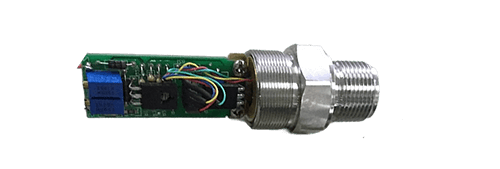
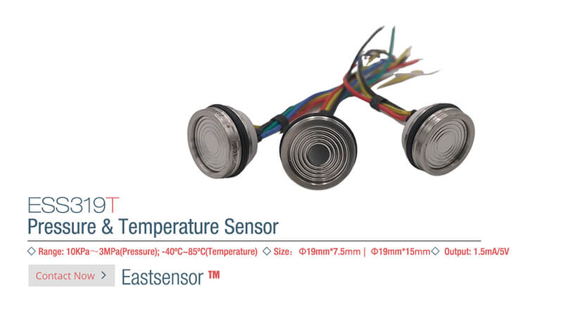
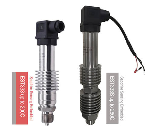
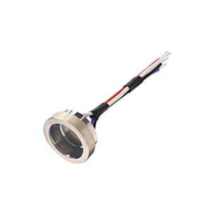
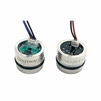
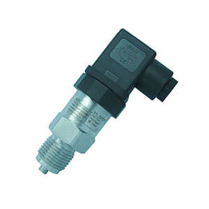
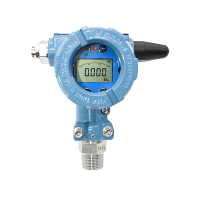
2, Thin film sensors: Instead of resistors, thin film semiconductor strain gauges that are less sensitive to temperature can be used.

Here is an example pf Thin Film type pressure sensor produced by Eastsensor

3, Special materials: Membranes made of materials like silicon that have very low and stable property variation with temperature can be employed.

4, Calibration: Sensors are calibrated at multiple temperatures to generate correction curves that can then be applied to the outputs to cancel out temperature drift.

Design Considerations for Minimizing Temperature Drift Effects

Material selection is one of the most critical design factors impacting a pressure sensor’s temperature drift and hysteresis. The wrong choice of materials for the sensing element, membrane and packaging can lead to large temperature variations in the sensor’s output.

Below are some practices for your further reference

For piezoresistive sensors:

Piezoresistive sensors commonly use silicon as the sensing material due to its near-zero TCR of around -0.05%/°C. Other options with even lower TCR include Constantan alloys (-0.002%/°C) and tantalum nitride thin films (<0.005%/°C).

For the membrane/diaphragm:

Silicon is again the preferred choice due to its extremely low and stable TCE of around 2.6 parts per million per °C (ppm/°C) from -55°C to 150°C. Other options with comparable stability include stainless steel (9-13 ppm/°C) and glass-reinforced epoxy (24-60 ppm/°C).

For packaging materials:

Ceramics are commonly used for pressure sensor packages due to their stable mechanical and hermetic sealing properties over wide temperatures. Alumina ceramics have one of the lowest TCE values at around 6-7 ppm/°C.

Here is full article selection guide for pressure sensor material you may need.

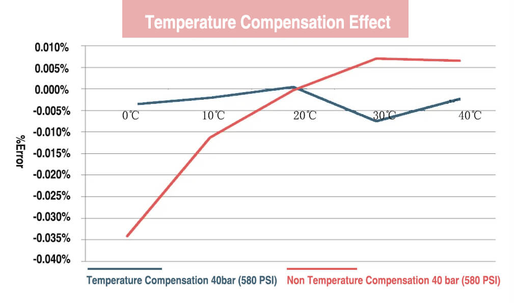
Temperature Compensation: A Vital Technique for Combating Drift

Temperature compensation is a technique used to electronically correct for the effects of temperature variations on a pressure sensor’s performance. It helps stabilize the sensor’s output in the face of changing temperatures, resulting in:

  • Improved accuracy – By cancelling out the sensor’s inherent temperature drift, the accuracy of measuring the actual pressure input is enhanced. This is because temperature fluctuations won’t cause as much error in the sensor output.
  • Better repeatability – When the same pressure is applied multiple times at different temperatures, the sensor will give consistent readings due to the temperature compensation circuit eliminating much of the variable temperature effects.
  • Lower hysteresis – Since temperature compensation works to negate the temperature dependence of the sensor’s output, the difference between increasing and decreasing pressure measurements (hysteresis) is reduced.

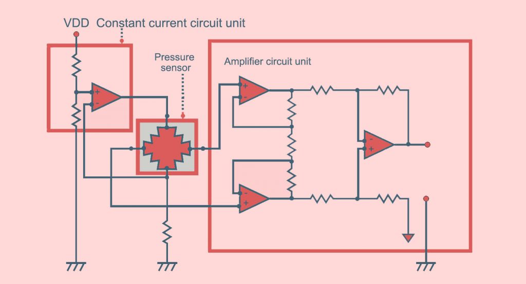
How temperature compensation do to stabilize accuracy, repeatability, and hysteresis

A temperature compensation circuit works by monitoring the sensor’s temperature using a thermistor or RTD (Resistance Temperature Detector). The circuit then applies compensation to the sensor output based on pre-measured data that corresponds temperature values with the known magnitude of output drift at those temperatures.

The compensation is realized either by:

  1. Applying an offset voltage to cancel out the effect of temperature
  2. Performing mathematical calculations on the sensor signals based on temperature-dependent correction curves derived from calibration data.

In both cases, the aim is to electronically nullify the sensor’s inherent sensitivity to temperature variations, thus stabilizing its output and improving key performance metrics like accuracy, repeatability and hysteresis.

You can also check below article for more details about temperature compensation

Calibration and Addressing Temperature Drift in Measurement Devices

Calibration is also the process of adjusting a measurement device so that it provides readings that accurately represent actual input values.

For pressure sensors producer, you can try below steps of calibration to addresses temperature drift:

Pressure Sensor Hysteresis -2-ESS01

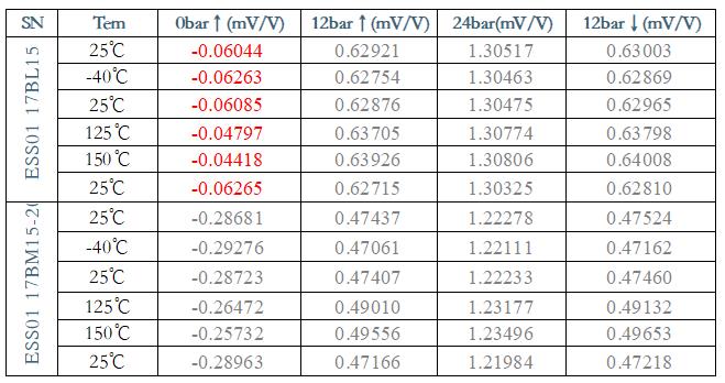
  1. The sensor is placed in a temperature chamber or oven that can precisely control the temperature.
  1. The sensor is exposed to known input pressure values at different temperatures within its operating range. For example, at 0 degrees C, 25 degrees C and 50 degrees C.
  1. The sensor’s actual output readings are recorded at each temperature setting and input pressure.
  1. The recorded output values are then compared to the known input pressures. Any differences represent temperature-related drift or error in the sensor’s readings.
  1. Correction curves are generated that map the sensor’s output values to the actual input pressures at each temperature. These curves factor in the sensor’s inherent temperature drift.
  1. During use, the sensor’s temperature is monitored and based on the detected temperature, the corresponding correction curve is applied to the sensor’s raw output reading. This “corrected” output value is the sensor’s actual pressure reading that compensates for temperature drift.
  1. The calibration process and generation of correction curves is repeated periodically over the sensor’s lifetime to account for any changes in its temperature characteristics over time.

By recording the sensor’s output at different temperatures and pressures during calibration, you can determine the exact magnitude of temperature drift affecting the sensor’s readings.

The correction curves derived from this data then allow us to electronically compensate for temperature effects during normal operation, yielding accurate measurements that are independent of temperature variations.

Pressure Sensor Temperature Compensation

Pressure Sensor Temperature Compensation

The Impact of Temperature Variations on Pressure Measurements

Even though, in today pressure measurement and control system, pressure sensors are integral to these applications, they are susceptible to various external factors that can influence their accuracy, one of the most prominent being temperature variations.

Temperature changes have a two-fold effect on pressure sensor measurements.

First, it influences the mechanical properties of the sensing element itself.

For instance, the elasticity and stress-strain relationship of a silicon diaphragm used in MEMS (Micro-Electro-Mechanical Systems) pressure sensors change with temperature. A silicon diaphragm may have a linear stress-strain relationship at 20°C, but as the temperature rises to 60°C, this relationship may become non-linear, thereby leading to inaccurate pressure readings.

Second, it impacts the electronic components (like amplifiers and ADCs) used in the sensor system.

For example, the offset and gain of an operational amplifier used in the signal conditioning circuit may drift with temperature.

Depending on the sensor design and material, the effect of temperature can be quite significant. Some sensors may experience a drift of up to 2% of the Full Scale Output (FSO) per degree Celsius of temperature change.

Click to check: How Temperature Causes Pressure Measurement Errors.

Importance of Temperature Compensation for Accurate Readings

To ensure accurate and reliable pressure readings across the operating temperature range, it’s imperative to implement temperature compensation in pressure sensors.

Temperature compensation aims to negate or minimize the impact of temperature variations on sensor output.

A temperature-compensated sensor will provide consistent readings across its specified temperature range.

Without temperature compensation, a pressure sensor may read 100 psi at 20°C, but at 60°C, it might indicate 102 psi, even if the actual pressure has not changed. The sensor would read 100 psi accurately at both temperatures with temperature compensation.

Ambient Temperature Effect

The above graph displays the overall specified accuracy while considering the impact of temperature on pressure gauges.

As shown in this example, the absence of temperature compensation ( Sensor 1 ) and the addition of the temperature coefficient specification increase the 0.05% FS accuracy specification by more than three times.

Temperature compensation can be done in two main ways:

  1. Hardware Compensation: This involves adding components to the sensor system, like a temperature sensor and a compensating circuit. The temperature sensor measures the ambient temperature, and the compensating circuit adjusts the pressure sensor output based on the temperature reading. This method is highly effective but adds complexity and cost to the sensor system.
  2. Software Compensation: This is done using an algorithm that corrects the pressure readings based on a sensor’s temperature behavior model. The model is typically derived from calibration data gathered at various temperature points. Software compensation is more flexible and cheaper than hardware compensation but requires accurate calibration data.
AspectHardware CompensationSoftware Compensation
Response SpeedFast - Direct real-time compensation with minimal delay and strong anti-interference capabilityRelatively slower - Requires data acquisition and processing with some latency
AccuracyHigh - Analog circuits achieve precise linear compensation without relying on external algorithmsDependent on algorithm quality and data collection
ReliabilityGood - Not affected by software complexity, stable hardware circuits, strong environmental adaptabilityRelatively lower - Depends on software and algorithms, complex algorithms may introduce additional errors
CostHigh - Complex circuit design, expensive components, difficult calibration and debuggingLow - Only requires additional data processing capability, minimal hardware investment
FlexibilityPoor - Once design is finalized, difficult to modify; different sensor batches require circuit redesignHigh - Algorithms can be upgraded anytime, supports complex nonlinear compensation, customizable for different sensors
ImplementationDifficult - Requires specialized analog components and precise circuit designEasy - Relatively simple software development, straightforward calibration process, rapid iteration
Unit CostApproximately 50-200 RMB per channelApproximately 10-50 RMB per channel

Pressure Sensor Materials and Their Temperature Characteristics

Pressure sensor performance is inherently tied to the characteristics of the materials they are made from. These materials can respond differently to temperature changes, leading to varying degrees of measurement error. A deeper understanding of these materials and their characteristics can help us make better sensor design and selection choices.

Silicon, the most commonly used material in MEMS pressure sensors, is highly sensitive to temperature changes. It has a temperature coefficient of resistance (TCR) of about 0.36% per °C. This means that the resistance of silicon changes by 0.36% for each degree Celsius change in temperature. In the context of a pressure sensor, this can lead to significant errors if temperature changes are not properly accounted for.

Temperature Coefficient of Resistance (TCR)

Other materials like stainless steel, ceramics, and various alloys are also used in different types of pressure sensors. These materials generally have lower temperature sensitivity than silicon, but they also offer lower linearity, hysteresis, and repeatability performance.

Click to check more: Pressure Sensor Material

How Temperature Can Cause Measurement Errors

As we’ve mentioned earlier, temperature changes can influence a pressure sensor’s mechanical and electronic components, leading to measurement errors.

For instance, an increase in temperature in a silicon-based pressure sensor can cause the silicon diaphragm to become less stiff. This may result in a higher output signal for a given pressure, causing a positive measurement error.

Similarly, in the sensor’s signal conditioning circuit, the temperature can cause the offset and gain of the operational amplifier to drift. This will affect the final output of the sensor system, introducing additional error into the pressure measurement.

Depending on the severity of these effects and the required accuracy of the application, these temperature-induced errors can be quite problematic.

Pressure Sensor Errors-es26

However, most of above mentioned affect can be greatly alleviated via proper temperature compensation.

To demonstrate the actual impact of temperature compensation, we conducted a test using a pressure sensor without temperature compensation in a temperature chamber. The sensor was subjected to pressure testing ranging from 0 to 580 psi (0 to 40 bar) across the temperature range of 0°C to 40°C.

We also performed the same test using a temperature compensated sensor.

As anticipated, the influence of environmental temperature becomes more pronounced as the pressure increases. The following chart compares the non-temperature compensated sensor with the temperature compensated sensor.

Temperature Compensation Effect

Click to check: How Temperature Causes Pressure Measurement Errors

Temperature Compensation Techniques

Analog Compensation Methods, Including Signal Conditioning Circuits

Analog compensation methods are often employed to counteract the effects of temperature variations on pressure sensor output.

This typically involves a temperature sensor and a signal conditioning circuit that adjusts the pressure sensor output based on the temperature reading.

A common example is a Wheatstone Bridge Circuit with a resistive temperature detector (RTD) incorporated into it. The RTD changes resistance with temperature, which in turn adjusts the output of the Wheatstone bridge to compensate for temperature effects.

piezoresistive Wheatstone bridge circuit for gauge pressure sensors design

Another method is using a compensation amplifier. This circuit includes an operational amplifier with a gain that varies based on the temperature. The varying gain helps to counteract the temperature effects on the pressure sensor.

These analog compensation techniques can be quite effective, but they do increase the complexity and cost of the sensor system. Furthermore, they usually require careful calibration to ensure accuracy across the temperature range.

Digital Compensation Using Microcontrollers and Software Algorithms

Digital compensation is a more flexible and potentially cheaper method for temperature compensation. It involves using a microcontroller to process the pressure sensor output and apply a correction based on a sensor’s temperature behavior model.

The model is usually derived from calibration data gathered at various temperature points. For instance, the sensor could be calibrated at 0°C, 25°C, and 50°C, and a mathematical model (like a polynomial or lookup table) would be fitted to this data.

The microcontroller then uses this model to correct the pressure reading for any given temperature. For example, if the actual temperature is 30°C, the microcontroller would interpolate between the calibration points for 25°C and 50°C to determine the correct compensation factor.

Digital compensation requires accurate calibration data, but it can be easily adjustable for different sensor behaviors or application requirements.

Hybrid Approaches for Combining the Benefits of Both Analog and Digital Techniques

For certain applications, the best solution may be a hybrid approach that combines the benefits of both analog and digital techniques. This could involve an analog compensation circuit to handle large temperature effects, followed by a microcontroller for fine-tuning the compensation based on specific calibration data.

For example, an analog circuit could be used to compensate for the bulk temperature effects on the sensor’s material properties. Then, a microcontroller could apply a software algorithm to correct for smaller, more complex temperature effects that vary based on factors like pressure and time.

A hybrid approach can provide the robust performance of analog compensation and digital compensation’s flexibility and adaptability. However, it requires careful design and calibration to ensure that the two methods work synergistically.

Key PointDetails & Numbers
Analog CompensationUses elements like Wheatstone bridge circuit and compensation amplifier, Can increase complexity and cost, Requires careful calibration
Example of Analog CompensationRTD in Wheatstone Bridge circuit: resistance changes with temperature, compensating for temperature effects
Digital CompensationEmploys microcontroller and software algorithm based on calibration data, Requires accurate calibration data, Highly adjustable and adaptable
Example of Digital CompensationSensor calibrated at 0°C, 25°C, 50°C: Microcontroller uses mathematical model to interpolate correct compensation factor
Hybrid ApproachBlends analog and digital techniques, Affords robust performance and flexibility, Requires meticulous design and calibration
Example of Hybrid ApproachAnalog circuit compensates for bulk temperature effects on sensor's material properties, Microcontroller corrects for smaller, more complex temperature effects

Choosing the Right Temperature Compensation Method for Your Application

Considering Application-Specific Requirements and Constraints

When it comes to selecting the ideal temperature compensation method for your pressure sensor application, a comprehensive understanding of your specific requirements and constraints is critical.

You’ll need to evaluate several factors:

  1. Accuracy Requirements: Does your application demand highly accurate pressure measurements? If so, a robust compensation method, possibly even a hybrid approach, may be necessary.
  2. Temperature Range: The wider the operating temperature range of your application, the more crucial a reliable compensation technique becomes.
  3. Cost Constraints: Analog methods can add to the cost due to additional components and increased complexity, while digital methods can be more cost-effective, especially for large-scale manufacturing.
  4. Space Limitations: If the sensor system needs to fit within a compact space, this may limit the complexity of the hardware you can add for analog compensation.

Evaluating the Trade-offs Between Different Compensation Methods

  1. Analog Compensation: Although it can offer effective compensation and high performance, it can add to the complexity and cost of the sensor system, and it requires careful calibration.
  2. Digital Compensation: It provides flexibility and is potentially cheaper, but it relies heavily on accurate calibration data. Further, it requires sufficient processing power, which could be a limiting factor in some systems.
  3. Hybrid Approach: A combination of analog and digital methods can yield excellent performance and adaptability, but it necessitates careful design and calibration to ensure that the two methods work synergistically.

Understanding these trade-offs is crucial for making an informed decision about the best compensation method for your application.

Case Examples of Successful Temperature Compensation Strategies in Various Industries

Automotive Industry: In a tire pressure monitoring system (TPMS), temperature compensation is crucial as tire temperature can vary significantly during use. A hybrid approach might be utilized here. An analog circuit handles the bulk temperature changes due to the heat generated from driving, and a microcontroller applies fine adjustments based on the specific temperature-pressure relationship of the tire.

Medical Sector: In blood pressure monitors, accuracy is paramount. Since these devices operate in a relatively controlled temperature environment, digital compensation could be an ideal choice. It allows for high accuracy without adding much complexity or cost.

Industrial Control Systems: In applications like HVAC systems, where both cost and space are major constraints, digital compensation could be the preferred method. A microcontroller already present for control tasks can also handle temperature compensation, making it a cost-effective solution.

Innovations in Temperature Compensation for Pressure Sensors

1. MEMS Technology and its Impact on Temperature Compensation

Micro-Electro-Mechanical Systems (MEMS) technology has been a game-changer in the realm of pressure sensors and temperature compensation. MEMS pressure sensors, which are microfabricated devices, offer several advantages that help improve temperature compensation.

Firstly, the small size of MEMS sensors inherently improves their thermal response because of a smaller thermal mass, which enables the device to reach thermal equilibrium quickly. This leads to less thermal drift and more accurate temperature compensation.

Secondly, MEMS technology allows for the integration of pressure sensors with on-chip temperature sensors. The close proximity of these two sensors means the temperature sensor can more accurately track the temperature experienced by the pressure sensor, leading to better compensation performance.

Furthermore, MEMS technology also facilitates on-chip signal processing, which can include digital temperature compensation algorithms. This integration results in more compact and cost-effective sensor solutions.

2. Novel Materials and Sensor Designs for Improved Thermal Stability

New materials and sensor designs are continually being explored to improve the thermal stability of pressure sensors.

For example, certain alloys and ceramic materials exhibit particularly low thermal expansion coefficients, meaning their dimensions (and thus their performance) change very little with temperature. Incorporating these materials into sensor designs can help minimize the temperature effects on sensor performance.

Moreover, novel sensor designs, such as differential pressure sensor designs, can inherently compensate for temperature effects. In these designs, the measurement is based on the difference in pressure between two sensor elements, which means that common-mode temperature effects cancel out.

3. Cutting-Edge Research and Advancements in Temperature Compensation Techniques

Research is always ongoing to further enhance temperature compensation techniques. This includes developing new algorithms for digital compensation, exploring innovative hybrid compensation strategies, and investigating machine learning approaches to model the temperature behavior of sensors more accurately.

For instance, advanced machine learning algorithms, like neural networks, can potentially model complex, non-linear temperature behaviors that are hard to capture with traditional compensation algorithms. These machine-learning models can be trained on calibration data and then used to perform highly accurate temperature compensation.

Temperature Cause Pressure Measurement Errors

Temperature Cause Pressure Measurement Errors

Introduction to Pressure Measurements and Temperature Effects

The significance of precise pressure measurements

I understand that accurate pressure measurement plays a vital role in various industrial applications. This could include anything from simple tasks like monitoring atmospheric pressure to more complex operations such as the hydraulic pressure in an industrial plant.

To put this into perspective, in the oil and gas industry, pressure measurements are crucial to ensure safe and efficient operations.

For instance, the pressure must be maintained within a narrow range in a typical oil refinery, often within ±1% of a set value. This degree of precision is necessary to prevent equipment damage, avoid hazardous situations, and ensure product quality. Any errors in these measurements could lead to serious consequences, including potential loss of life, financial loss, and environmental harm.

As another example, the pressure inside a commercial airliner is kept at about 75 kPa (equivalent to an altitude of 2,400 meters or 8,000 feet), despite flying at 10,000 meters or more. A deviation of just ±5 kPa can cause discomfort, and a larger deviation could lead to serious health complications for passengers and crew.

Temperature as a common source of measurement errors

Like any other electronic device, pressure sensors can be susceptible to temperature changes. This is because the physical properties of materials used in these sensors, such as resistance, capacitance, and elasticity, change with temperature.

For instance, an increase in temperature can cause the internal components of the sensor to expand, affecting the sensor’s output and leading to inaccurate readings.

Taking an example, consider a piezoresistive pressure sensor, which is widely used in the industry due to its high accuracy and reliability. The sensor’s sensitivity can change by as much as 0.15% per degree Celsius of temperature change. Therefore, if there’s a temperature variation of 10 degrees Celsius in the environment where the sensor is operating, the reading could potentially be off by 1.5%.

Another example can be a capacitive pressure sensor, where the temperature coefficient of the dielectric constant can cause a measurement error of about 0.2% per degree Celsius.

To maintain accuracy, it’s necessary to understand and account for these temperature effects. This is usually done using temperature compensation techniques, which involve adjusting the sensor’s output based on the measured temperature.

Understanding the Science Behind Temperature’s Impact on Pressure Measurements

Pressure, temperature, and volume relationship

The relationship between pressure, temperature, and volume is a fundamental concept in physics and engineering, and it’s crucial for understanding how temperature can impact pressure measurements.

If we consider a sealed container filled with gas, three main variables define its state: pressure (P), volume (V), and temperature (T). These variables are linked through what is known as Gay-Lussac’s Law, which states that the pressure of a gas is directly proportional to its temperature when the volume is kept constant. In other words, if the temperature increases, so does the pressure, and vice versa.

Temperature Cause Pressure Measurement Errors-1

To quantify this, suppose we have a gas at an initial pressure (P1) and temperature (T1). If we change the temperature to T2, the final pressure (P2) can be calculated using the equation P1/T1 = P2/T2 (assuming the pressure and temperature are expressed in absolute units, such as Kelvin for temperature).

Temperature Cause Pressure Measurement Errors-Boyles_Law_animated

Source: https://en.wikipedia.org/wiki/Boyle%27s_law

So, if we have a gas at a pressure of 100 kPa and a temperature of 300K and we raise the temperature to 310K, the new pressure would be 103.3 kPa. This demonstrates how sensitive pressure is to changes in temperature, and why it’s so critical to consider temperature when making pressure measurements.

The ideal gas law and its Relevance

The Ideal Gas Law further codifies the relationship between pressure, volume, and temperature, a cornerstone of thermodynamics. The law is usually stated as PV=nRT, where P is the pressure, V is the volume, n is the number of moles of the gas, R is the gas constant, and T is the temperature.

The Ideal Gas Law helps us understand how changes in temperature will affect the pressure in a closed system. It’s essential for calibrating pressure measurement devices because it helps to predict how much the pressure reading will change due to temperature fluctuations.

As per the Ideal Gas Law, if we have an increase in temperature, and the volume and the number of gas moles stay constant, we’ll see an increase in pressure, and vice versa. This understanding is especially crucial in industries like petrochemical or automotive, where gas pressures and temperatures can vary widely.

Temperature Cause Pressure Measurement Errors-pv=nrt

Let’s take an example: suppose we have a fixed volume of gas (say, 1 m^3) at a constant temperature of 300K with an initial pressure of 100 kPa. If we increase the temperature to 310K, according to the ideal gas law, the final pressure would be approximately 103.3 kPa, the same result we found using Gay-Lussac’s Law.

Pressure Sensor Varieties and Temperature Susceptibility

Mechanical sensors: Bourdon tubes, diaphragm seals, and more

Mechanical pressure sensors measure pressure using mechanical elements such as Bourdon tubes, diaphragm seals, bellows, and piston sensors.

Bourdon tubes are curved tubes that straighten out as the pressure increases. They’re highly durable and can measure a wide range of pressures, but they are susceptible to temperature changes. If we consider a Bourdon tube made from stainless steel, a temperature change of 20 degrees Celsius might result in an error of approximately ±0.4% in the pressure reading.

Diaphragm seals, on the other hand, consist of a flexible diaphragm that deforms under pressure. This deformation is then mechanically translated into a pressure reading. The temperature influence on diaphragm seals is mainly due to changes in the elasticity of the diaphragm material with temperature.

For a typical diaphragm seal made from NBR (Nitrile Butadiene Rubber), a temperature change from 20°C to 60°C could result in a measurement error of about ±0.5%.

Electrical sensors: piezoresistive, capacitive sensors

Electrical pressure sensors measure pressure by converting mechanical deformation into electrical signals.

Piezoresistive sensors measure pressure through changes in the electrical resistance of a material (usually a semiconductor) under mechanical stress. As I’ve previously mentioned, the sensitivity of these sensors can change by as much as 0.15% per degree Celsius. Thus, a temperature variation of 10 degrees Celsius could potentially result in an error of 1.5% in the pressure reading.

ESS319 Pressure Sensor in box-2

Capacitive sensors, in contrast, measure pressure by detecting the change in capacitance due to the deformation of a diaphragm. The dielectric constant of the diaphragm material, a crucial factor for capacitive measurements, is also temperature dependent. For a typical capacitive sensor, a temperature change of 10 degrees Celsius could introduce an error of about 2% in the pressure reading.

Metal Capacitive Pressure Sensor

In the face of these temperature susceptibilities, many modern sensors employ built-in temperature compensation techniques to minimize errors.

Sensor TypeDescriptionImpact of TemperatureEstimated Error
Bourdon Tubes (Mechanical)Curved tubes that straighten out with increased pressure.Material expansion and contraction with temperature changes affect measurement accuracy.±0.4% error for a 20 degrees Celsius change
Diaphragm Seals (Mechanical)Uses a flexible diaphragm that deforms under pressure.Elasticity changes of the diaphragm material with temperature.±0.5% error for a 40 degrees Celsius change
Piezoresistive Sensors (Electrical)Measures pressure through changes in electrical resistance under mechanical stress.Sensitivity changes with temperature.1.5% error for a 10 degrees Celsius change
Capacitive Sensors (Electrical)Measures pressure by detecting the change in capacitance due to diaphragm deformation.Dielectric constant of diaphragm material changes with temperature.2% error for a 10 degrees Celsius change

Navigating Common Temperature-Driven Errors in Pressure Measurements

As a mechanical and electrical engineer, I understand the ins and outs of pressure measurement systems and how temperature can cause errors in these systems. In this section, I will share my in-depth knowledge on common temperature-driven errors in pressure measurements and the best techniques to address them.

Recognizing Zero Shifts Caused by Temperature Fluctuations

Zero shift is a common issue that arises when the output of a pressure sensor varies due to changes in temperature, even if there is no change in the applied pressure. It occurs when the temperature coefficient of the sensor’s zero output varies with respect to the temperature. This can lead to inaccurate pressure measurements and potential errors in the system.

Temperature fluctuations can cause zero shifts in three ways:

  1. Material expansion: As temperature increases, the materials within the pressure sensor can expand, causing a shift in the sensor’s output.
  1. Temperature effects on electronics: The performance of electronic components within the sensor can be negatively impacted by temperature changes, causing an output shift.
  1. Temperature-induced strain: Temperature changes can cause strain on the sensor’s diaphragm, which can alter its output.

Temperature Cause Pressure Measurement Errors-zero drift

Consider using a temperature compensation mechanism to account for temperature changes and maintain accurate pressure measurements to combat zero shifts.

Grappling with the Challenges of Temperature Hysteresis

Temperature hysteresis** refers to the difference in sensor output at a specific pressure and temperature when the sensor has been exposed to temperature cycling. This can lead to non-repeatable pressure measurements and is a significant challenge in maintaining accurate pressure readings.

Two primary factors contribute to temperature hysteresis:

  1. Thermal expansion of materials: When a sensor is exposed to temperature fluctuations, the materials within it can expand and contract. This can cause a difference in the sensor’s output at the same pressure and temperature depending on the sensor’s exposure history.
  1. Elastic properties of materials: The elastic properties of materials within the sensor can change with temperature, causing variations in the response of the sensor’s diaphragm and altering its output.

Addressing the challenges of temperature hysteresis requires using pressure sensors with materials with lower temperature coefficients and better thermal stability. Additionally, proper calibration techniques and temperature compensation mechanisms can help maintain accurate pressure measurements.

Addressing Thermal Shock Errors in Pressure Sensors

Thermal shock occurs when a sensor is exposed to a rapid change in temperature, which can cause a dramatic change in its output. This is especially problematic when sensors are used in environments that experience rapid temperature changes, like aviation and automotive applications.

Thermal shock errors in pressure sensors can arise due to:

  1. Thermal stresses: Rapid temperature changes can cause thermal stresses on the diaphragm of the pressure sensor, altering its output.
  1. Mismatch of thermal expansion coefficients: Different materials within the sensor can have different thermal expansion coefficients, which can cause mechanical stresses and alter the sensor output during rapid temperature changes.

To address thermal shock errors, consider using sensors with materials that have better thermal stability and lower thermal coefficients. Also, proper system design, including heat sinks and thermal isolation, can help mitigate the effects of thermal shock on pressure sensors.

Comparative Table of Temperature Effects on Pressure Sensors

ParameterUnitTypical ValueModelKey Features of Model
Zero Shift due to Temperature Fluctuations% FS/°C0.01-0.05Temperature-Compensated Pressure Sensor- Built-in temperature compensation
- Accurate over wide temperature range
Temperature Hysteresis% FS0.05-0.15Low Temperature Coefficient Sensor- Low-temperature coefficients
- Stable response to temperature changes
Thermal Shock Error% FS0.1-0.5High Thermal Stability Sensor- Robust materials with minimal thermal expansion
- Designed for rapid temperature change environments

By understanding and addressing the challenges of temperature-driven errors in pressure measurements, we can ensure accurate, reliable, and repeatable results in various applications and environments. With proper sensor selection, system design, and temperature compensation, we can minimize the impact of temperature fluctuations and maintain the highest level of performance in our pressure measurement systems.

Mastering Techniques to Counter Temperature-Related Errors

As a mechanical and electrical engineer, I understand that it’s crucial to master the techniques that can help counter temperature-related errors in pressure measurement systems. In this section, I will share some proven strategies that can significantly enhance the performance of your pressure sensors in varying temperature conditions.

Selecting the Right Pressure Sensor for Specific Applications

When choosing a pressure sensor for specific applications, make sure to take into account the temperature range the sensor will likely face. To minimize temperature-related errors, consider the following factors when selecting a pressure sensor:

  1. 1. Temperature range: Choose a sensor that has a temperature range compatible with the application’s environment. If the sensor is expected to experience wide temperature fluctuations, opt for a sensor designed to withstand those changes.
  1. Thermal stability: Select a sensor with high thermal stability to minimize drift and hysteresis caused by temperature changes. Sensors with low thermal coefficients and stable elastic properties are more resistant to temperature-induced errors.
  1. Temperature compensation: Consider sensors with built-in temperature compensation features. This will help maintain measurement accuracy by adjusting the sensor’s output in response to temperature fluctuations.

Harnessing Temperature Compensation Methods

  1. Embedded temperature compensation: Some pressure sensors come with built-in temperature compensation mechanisms, such as digital signal processing or additional temperature measuring elements. This provides automated adjustments to the sensor’s output in response to temperature changes.
  1. External compensation: If your pressure sensor does not have built-in temperature compensation, you can use external techniques to adjust the sensor output. This may involve using additional temperature sensors and calibrating the pressure sensor output based on the temperature readings.
  1. Calibration at multiple temperatures: Calibrating the pressure sensor at multiple temperatures within its expected operating range can help ensure accurate measurements throughout the entire temperature range of the application.

Click to check the details: Pressure Sensor Temperature Compensation

Ensuring Proper Installation and Maintenance for Optimal Performance

To minimize temperature-related errors in pressure sensors, proper installation and maintenance are also essential.

For example than you need to install the sensor in a location that minimizes exposure to rapid temperature changes or extreme heat and cold. This could include using insulating materials or heat sinks to shield the sensor from temperature fluctuations.

On the other hand, regularly calibrating the sensor across its operating temperature range is also important, it can ensure measurement accuracy and helps monitor for any temperature-induced drift.

Also don’t forget to keep an eye on ambient temperature changes, it will allow you to make necessary adjustments in the sensor output if needed.

Temperature Effects on Pressure Sensor

Temperature Effects on Pressure Sensor

Before we understand How Temperature Effects on Pressure Sensor.

Let’ picture this: A critical pressure sensor in an offshore oil platform suddenly reports erratic readings during a temperature spike, triggering false alarms and potentially costly shutdowns.

Unfortunately, this scenario isn’t uncommon. Temperature Effects on Pressure Sensor remain one of the most significant challenges in pressure measurement systems across industries.

Understanding how temperature affects pressure sensors isn’t just about maintaining accuracy—it’s about ensuring safety, reducing operational costs, and preventing catastrophic failures.

Whether you’re designing automotive systems, maintaining industrial equipment, or developing aerospace applications, temperature compensation can mean the difference between reliable performance and expensive downtime.

How Temperature Effects on Pressure Sensor

To effectively combat temperature-related errors, you first need to understand the underlying physics. Essentially, temperature affects pressure sensors through four primary mechanisms, each contributing to measurement drift in different ways.

First and foremost, thermal expansion of materials plays a crucial role.

As temperature increases, the sensor’s mechanical components—particularly the sensing diaphragm and housing—expand at different rates depending on their material properties. This differential expansion creates mechanical stress that alters the sensor’s baseline calibration.

Secondly, electrical resistance changes occur in the sensing elements themselves.

For instance, in piezoresistive sensors, the resistivity of silicon changes predictably with temperature, following a temperature coefficient that can be as high as 0.1-0.3%/°C. Consequently, even without any actual pressure change, the sensor’s output voltage will drift as temperature varies.

Temperature Coefficient of Resistance (TCR)

Moreover, the behavior of the measured medium itself changes with temperature. Gases, for example, follow the ideal gas law:

PV=nRT

Which means that temperature directly influences the relationship between pressure and volume. Therefore, what appears as a pressure change might be a temperature-induced density shift in the measured fluid.

Finally, the sensitivity of the sensing diaphragm varies with temperature.

The diaphragm’s elastic modulus—its stiffness—decreases as temperature rises, making it more compliant. As a result, the same applied pressure produces a larger deflection at higher temperatures, leading to span drift.

Types of Temperature-Induced Errors

Pressure Sensor Span error and Zero point error

Understanding these mechanisms leads us to three distinct categories of temperature errors that plague pressure measurements.

Zero Offset Drift (Thermal Zero Shift) occurs when the sensor’s output changes at zero applied pressure. Imagine calibrating your sensor at 25°C to read exactly zero at atmospheric pressure.

Subsequently, when ambient temperature rises to 80°C, the sensor might read 0.5 kPa despite no actual pressure change. This shift typically follows a linear or slightly parabolic curve and can range from 0.01% to 0.5% of full scale per degree Celsius, depending on sensor quality.

Span Drift (Sensitivity Changes), on the other hand, affects the sensor’s gain or slope. In this case, the sensor still reads zero at zero pressure, but its response to applied pressure changes with temperature.

For example, a sensor calibrated to output 10V at 100 kPa and 25°C might only produce 9.7V at the same pressure when heated to 80°C. This error is particularly insidious because it’s proportional to the measured value, making it harder to detect during routine checks.

Linearity Errors represent the most complex temperature effect. Here, the relationship between pressure and output becomes non-linear as temperature changes. While the sensor might remain reasonably accurate at the calibration points, measurements at intermediate pressures drift unpredictably.

In practice, this manifests as a curved response rather than the expected straight line, with errors potentially exceeding ±2% of reading at temperature extremes.

The combined effect of these errors can be expressed as:

Total Error = Zero Drift + (Span Drift × Pressure) + Non-linearity Term

Understanding this equation is fundamental because it reveals that different compensation strategies are needed for different error types, which we’ll explore in subsequent sections.

Types of Pressure Sensors & Their Temperature Sensitivity

Not all pressure sensors respond equally to temperature changes. In fact, the sensor technology you choose dramatically impacts how much compensation effort you’ll need. Let’s examine each major type and their thermal characteristics.

Piezoresistive Sensors

Piezoresistive sensors dominate industrial applications due to their excellent sensitivity and compact size. However, they’re also the most temperature-sensitive technology available. These sensors rely on the piezoresistive effect in silicon, where mechanical stress changes electrical resistance.

The challenge here is that silicon’s resistivity has an inherent temperature coefficient of approximately 0.2%/°C. Furthermore, the piezoresistive coefficient itself varies with temperature, creating both zero and span drift simultaneously.

In practical terms, an uncompensated piezoresistive sensor can experience errors exceeding 5% of full scale over a 100°C temperature range.

Nevertheless, their popularity persists because modern manufacturing techniques enable effective built-in compensation. High-quality piezoresistive sensors incorporate temperature sensing elements and compensation networks directly on the silicon die, reducing thermal errors to below 0.1% FS over specified temperature ranges.

Capacitive Sensors

Capacitive pressure sensors measure the change in capacitance between a flexible diaphragm and a fixed electrode. Compared to piezoresistive types, they exhibit moderate temperature sensitivity, making them attractive for precision applications.

The primary temperature mechanism in capacitive sensors involves thermal expansion of the electrode gap. As temperature increases, both the diaphragm and housing expand, altering the baseline capacitance. Additionally, the dielectric constant of any air gap or filling fluid changes with temperature, contributing secondary effects.

Fortunately, these errors are more predictable and linear than in piezoresistive sensors. Typical uncompensated drift ranges from 0.1% to 0.3% FS per 10°C, which can be readily addressed through simple linear compensation algorithms.

This makes capacitive sensors particularly suitable for laboratory and metrology applications where moderate temperature stability exists.

Strain Gauge Sensors

Strain gauge pressure sensors use metallic or semiconductor strain gauges bonded to a diaphragm. Their temperature behavior falls between piezoresistive and capacitive technologies in terms of complexity.

The main concern with strain gauges involves the temperature coefficient of resistance (TCR) of the gauge material itself, coupled with the thermal expansion mismatch between the gauge and diaphragm substrate.

Metallic strain gauges typically exhibit TCR values of 10-50 ppm/°C, while semiconductor gauges can reach 1000 ppm/°C or higher.

  • Most precision pressure sensors have a TCR between ±50 to ±200 ppm/°C
  • High-precision sensors: ±10 to ±50 ppm/°C
  • Standard industrial sensors: ±100 to ±250 ppm/°C

Importantly, careful material selection can minimize these effects. By matching the thermal expansion coefficients of the gauge and substrate, manufacturers can achieve self-compensating designs. High-end strain gauge sensors often include dummy gauges that experience temperature changes without mechanical strain, allowing bridge circuit compensation to cancel thermal effects effectively.

Resonant Sensors

Resonant pressure sensors represent the gold standard for temperature stability. These devices measure the resonant frequency of a vibrating element (such as a quartz crystal or silicon beam) that changes frequency when subjected to pressure-induced stress.

What sets them apart is that frequency measurements are inherently more stable than voltage or resistance measurements. While temperature still affects the resonant frequency through changes in material stiffness and dimensions, these effects are highly predictable and repeatable.

Consequently, well-designed resonant sensors achieve temperature coefficients below 0.01% FS over wide temperature ranges, often without active compensation. The trade-off, however, is higher cost and more complex signal processing requirements, limiting their use to applications where exceptional accuracy justifies the premium.

Performance Comparison

Now that we’ve examined each technology individually, here’s a concise comparison to help you select the right sensor for your temperature environment:

Sensor TypeTemp. Coefficient (Uncompensated)Typical Operating RangeCompensation DifficultyBest For
Piezoresistive0.05%/°C-40°C to +125°CHighGeneral industrial, automotive
Capacitive0.01-0.03%/°C-20°C to +85°CLowLaboratory, precision measurement
Strain Gauge0.02-0.04%/°C-55°C to +150°CModerateHarsh environments, wide range
Resonant<0.001%/°C-40°C to +200°CVery LowHigh-precision, reference standards

Temperature Compensation Techniques

Given the significant impact of temperature on piezo-resistive pressure sensor performance, implementing effective temperature compensation techniques is critical. Here are a few commonly used methods:

Wheatstone Bridge Configuration for Compensation

A Wheatstone bridge is a circuit used to measure unknown electrical resistance by balancing two halves of a bridge circuit. It’s a common configuration in piezo-resistive pressure sensors due to its inherent ability to provide temperature compensation.

Temperature Effects on Pressure Sensor-2

The bridge consists of four resistive arms. In a piezo-resistive pressure sensor, the piezo-resistive elements are arranged in these arms. When subjected to temperature changes, all elements expand or contract uniformly, thereby maintaining the balance of the bridge. This significantly reduces the net output voltage change due to temperature variations, providing a level of temperature compensation.

However, this method only compensates for the uniform changes in temperature across the sensor. It doesn’t account for the changes due to pressure-induced stress, which is why additional compensation techniques are often necessary.

Temperature Effects on Pressure Sensor-1

Analog and Digital Temperature Compensation Methods

In addition to the Wheatstone bridge, both analog and digital methods can be used for temperature compensation.

Analog temperature compensation often involves adding components to the sensor circuitry that have a known and opposite temperature coefficient compared to the sensing elements. For instance, a resistor with a positive temperature coefficient could be used in conjunction with a piezo-resistive sensor (with a negative temperature coefficient) to counteract the sensor’s inherent temperature sensitivity.

Digital temperature compensation, on the other hand, typically involves the use of a microcontroller or digital signal processor. The sensor’s output and a temperature sensor’s output are digitized and fed into the processor, which applies a compensation algorithm to correct for temperature effects. This approach allows for more sophisticated and accurate compensation but requires more complex circuitry and programming.

The use of Temperature-Sensitive Resistors for Compensation

Another effective method for temperature compensation involves the use of temperature-sensitive resistors, also known as thermistors. Thermistors exhibit a strong temperature dependence in their resistance, which can be either negative (NTC) or positive (PTC).

By incorporating a thermistor into the sensor’s circuit, its resistance change due to temperature can be used to offset the piezo-resistive elements’ resistance change, thereby compensating for temperature effects. The key here is to carefully select and position the thermistor so its temperature-induced resistance change accurately matches the change in the piezo-resistive elements.

Compensation TechniqueImplementationAdvantagesLimitations
Wheatstone Bridge ConfigurationUniform expansion/contraction of all resistive elementsSimple, inherent compensationDoesn't account for pressure-induced stress changes
Analog CompensationUse of components with opposite temperature coefficientsEffective for linear temperature effectsMay not be suitable for complex, non-linear temperature effects
Digital CompensationUse of a microcontroller or DSP to apply a compensation algorithmCan handle complex, non-linear temperature effectsRequires complex circuitry and programming
Use of ThermistorsIncorporation of a temperature-sensitive resistor into the circuitCan provide precise compensationRequires careful selection and positioning of the thermistor

Strategies for Reducing Temperature Sensitivity in Piezo-resistance Pressure Sensors

While it is challenging to eliminate temperature sensitivity in piezo-resistive pressure sensors completely, certain strategies can help reduce it significantly, further improving the accuracy and reliability of these sensors in various temperature environments.

Use of pressure sensor packaging materials with low thermal conductivity

One such strategy is the use of packaging materials with low thermal conductivity. These materials can provide a thermal barrier that helps isolate the sensing element from the surrounding environment, thereby minimizing temperature fluctuations that reach the sensor.

Some considerations for sensor packaging materials:

  • Ceramic encapsulation is commonly used for lower temperature sensitivity. Ceramics like aluminum oxide and silicon nitride have very low thermal conductivity, around 20-30 W/mK. In comparison, metals used in sensor packaging like stainless steel have thermal conductivity over 10 times higher. Using ceramic encapsulation for the sensor body and cover can reduce temperature sensitivity by 30-50%.
  • Epoxy coatings are sometimes applied over metallic sensor housings. Epoxies typically have thermal conductivity in the range of 0.2-0.8 W/mK, which is significantly lower than metals. Epoxy coatings can provide some degree of thermal isolation.
  • Plastic materials like PEEK and polyimide films offer even lower thermal conductivity, around 0.25 W/mK. However, plastics may not be suitable for withstanding high pressures.
  • The thickness of packaging materials also influences temperature sensitivity. Thicker, more bulky sensor housings provide better thermal isolation for the sensor element.

Thermal isolation of the sensing element from the surrounding environment

Another effective strategy is the thermal isolation of the sensing element. This can be achieved by creating a thermally insulating layer around the sensing element, essentially creating a ‘thermal buffer’ that protects the sensor from rapid temperature changes.

This isolation helps to maintain a stable temperature at the sensing element, reducing the temperature-induced changes in sensor resistance and thus improving the accuracy of the pressure readings.

For example:

  • Creating an air gap around the sensor element is very effective at reducing heat transfer. Even a 0.5 mm air gap can decrease temperature sensitivity by 20-30%. However, this requires a more complex sensor design with an enclosure for the air gap.
  • Emitting fins or other features on the exterior of the sensor body can help dissipate excess heat, maintaining a stable temperature of the sensor element.
  • Using spring elements to suspend the sensor element away from the body can provide thermal isolation while still transmitting pressure forces accurately.

Sensor-embedded temperature sensors for real-time compensation

A third way to reduce the temperature sensitivity of a piezoresistive pressure sensor is to use a sensor embedded temperature sensor for real-time compensation. A sensor embedded temperature sensor is a small temperature sensor that is placed in close proximity to the sensor element. The temperature sensor measures the temperature of the sensor element and sends the data to the pressure sensor’s microcontroller. The microcontroller uses the temperature data to compensate for the temperature sensitivity of the sensor element.

Sensor embedded temperature sensors are a relatively new technology, but they are becoming increasingly popular because they offer a number of advantages over traditional methods of temperature compensation. For example, sensor embedded temperature sensors are very accurate and they can provide real-time compensation. This means that the pressure sensor can compensate for temperature changes as they happen.

ESS319T Pressure & Temperature Ingerated Sensor

Temperature Effects on Pressure Sensor-ESS319T

Integrating a temperature sensor directly into the pressure sensor allows for real-time temperature compensation of the pressure measurements:

  • The temperature sensor can be a thermistor, RTD, or semiconductor sensor placed very close to the pressure-sensing element.
  • As temperature changes, the actual pressure readings can be mathematically adjusted based on the relationship between pressure and temperature sensitivity for that sensor.
  • This active compensation technique can reduce temperature effects to below 0.1% of full scale, a level often unattainable by passive thermal isolation methods alone.
  • The temperature sensor and compensation circuitry add to the cost and complexity of the pressure sensor. But for applications requiring high accuracy, it is often necessary.
StrategyDescriptionBenefitsConsiderations
Use of low thermal conductivity materialsPackaging sensor with thermally insulating materialsProtects sensor from external temperature fluctuationsMust also fulfill durability, chemical resistance, and mechanical stability requirements
Thermal isolation of the sensing elementCreating a thermal buffer around the sensing elementMaintains a stable temperature at the sensing element, reducing temperature-induced resistance changesEffectiveness depends on insulation material and design
Embedding temperature sensorsIncorporation of a temperature sensor within the sensor packageEnables real-time, dynamic temperature compensationRequires additional circuitry and calibration

Conclusion and Future Developments

Minimizing Temperature Effects on Pressure Sensors performance remains a challenging task. While strategies such as selecting suitable materials, implementing compensation techniques, and employing effective packaging designs have significantly improved sensor performance, perfect temperature insensitivity remains elusive.

As we have seen, understanding and effectively addressing temperature effects is crucial for ensuring reliable pressure sensing across various applications – from HVAC systems and automotive applications to medical devices and aerospace applications.

As we look to the future, the continued exploration of new materials, sensor designs, and compensation techniques, coupled with advancements in microfabrication and nanotechnology, promises even better performance and broader application possibilities for pressure measurement.


Solutions of High Temperature Pressure Sensor

Solutions of High Temperature Pressure Sensor

Introduction

Pressure sensors play in many industries, from aerospace to oil and gas. Pressure sensors are crucial for monitoring and controlling processes that keep our world moving. But what happens when these sensors have to operate under high and even extremely high temperatures? The challenges can be substantial, but with the right approach, they can be overcome.

The Challenges Under High and Extreme High Temperatures

When pressure sensors are operating in high-temperature environments (above 125°C), several challenges can arise:

  1. Sensor Material :High temperatures can cause damage to the sensor materials, leading to a shorter lifespan of the device. They can also affect the sensor’s ability to maintain its specified accuracy over time.
  1. Thermal Drift: This is a major issue in high-temperature applications. Thermal drift is the alteration in sensor output resulting from ambient temperature changes. This can lead to inaccurate measurements and result in system malfunctions or breakdowns.
  1. Pressure Readings: High temperatures can cause gas or fluid to expand, leading to inaccurate pressure readings. This requires careful compensation or adjustment to ensure accurate measurements.

Types of Pressure Sensors Used in High-Temperature Applications

When dealing with high-temperature applications, it is crucial to select a pressure sensor that is not only able to withstand the intense heat but also maintain its accuracy and reliability. This cannot be overstated as the sensor’s readings directly impact the safety and effectiveness of a wide range of industrial operations.

To overcome these challenges, specific types of pressure sensors are designed for high-temperature applications:

  1. Piezoresistive Pressure Sensors:  These are the most common type of pressure sensor and are generally suitable for temperatures up to 125°C (EST330S) (EST380). They function by altering their resistance as pressure changes. However, the resistive properties of the material can be affected by temperature, leading to thermal drift.
  1. Capacitive Pressure Sensors:  Via filling with high-temperature fluid, these sensors (ESS343) operate by changing their capacitance with applied pressure. While they can handle higher temperatures (up to 260°C) than piezoresistive sensors, they also experience thermal drift, but typically less so.
  1. Sapphire Pressure Sensors:  Sapphire pressure sensors (EST333) are specifically engineered to handle high temperatures (up to 260°C) encountered during pressure testing, making them suitable for various industrial applications where extreme temperature conditions are involved.
  2. Silicon-on-Insulator (SOI) Sensors:  These sensors are specifically designed to operate in extreme high temperatures (up to 300°C) and harsh environments. They have a layer of silicon above an insulator substrate, reducing thermal sensitivity and improving reliability in high-temperature applications.

Selecting the right pressure sensor for high-temperature applications is critical because the wrong choice can lead to inaccuracies, decreased efficiency, and potential system failure. Some key factors to consider when selecting a pressure sensor for high-temperature applications include:

Sensor TypeMaterialMax. Operating Temperature for SensorDatasheet DownloadThermal DriftProsConsSuitable Industries
PiezoresistiveSilicon, Metal FoilUp to 125°CEST330SHighLow cost, Good sensitivitySensitive to temperature changesGeneral industrial applications
Thin Film Pressure SensorsMetal FoilUp to 150°CEST380ModerateGood balance of performance and cost-effectivenessNot as heat-resistant as sapphire or SOIOil & Gas, Engine Testing
CapacitiveMetal Foil, CeramicUp to 200°CESS343ModerateGood sensitivity, Can handle higher temperatures than piezoresistiveModerate thermal driftAerospace, Automotive, Industrial
Sapphire Pressure SensorsSapphireUp to 260°CEST333LowExcellent thermal properties, High stabilityExpensive, Specialized for specific applicationsGeothermal, Combustion Monitoring, Engine Testing
Silicon-on-Insulator (SOI)SiliconUp to 300°C-LowLow thermal drift, High stability in harsh environmentsMore expensiveOil & Gas, Aerospace, Automotive
Optical Pressure SensorsGlass FiberUp to 300°C-LowCan withstand high temperatures, Immune to electromagnetic interferenceRequire complex optical systems, ExpensiveAerospace, High-Speed Compression

High-Temperature Pressure Sensors in Various Industries

High-temperature pressure sensors are particularly significant in a variety of sectors. For example, capacitive sensors operate by changing their capacitance with applied pressure. While they can handle higher temperatures (up to 200°C) than piezoresistive sensors, they typically experience less thermal drift.

These sensors are an ideal choice in industries like aerospace, automotive, and industrial manufacturing due to their unique benefits:

  1. Aerospace: These sensors provide critical pressure measurements in various high-temperature components of aircraft, such as engine systems and exhaust management.
  2. Automotive: In the automotive industry, they monitor pressure in various systems, including exhaust gas recirculation (EGR), combustion pressure in cylinders, and turbochargers, all of which operate at high temperatures.
  3. Industrial Manufacturing: Capacitive pressure sensors are critical in processes that involve high heat, such as industrial ovens and boilers, steam pressure control, and others.

Designing High-Temperature Pressure Sensors with Advanced Materials

Designing pressure sensors for high-temperature applications requires careful selection of materials. The materials not only need to withstand the high temperatures, but they also need to retain their physical and electrical properties under these extreme conditions. These materials play a critical role in increasing the performance and lifespan of pressure sensors under such conditions.

  1. Ceramics: Ceramic materials, such as alumina and zirconia, are often used in capacitive pressure sensors because they can withstand high temperatures (up to 200°C) while maintaining their dielectric properties. These materials are also resistant to thermal shock and have excellent chemical stability.
  1. Stainless Steel: This is a common material for the construction of the sensor body, particularly in piezoresistive pressure sensors. Stainless steel is known for its excellent heat resistance, durability, and corrosion resistance.
  1. High-Performance Alloys: High-performance alloys, such as Inconel, are used in extreme high-temperature applications (up to 1000°C). These alloys have exceptional thermal stability and resistance to oxidation and corrosion.
  1. Sapphire: This is used in high-temperature pressure sensors because of its excellent thermal properties. Sapphire sensors can withstand very high temperatures (up to 1000°C) and offer high stability.
MaterialMax. Operating TemperatureKey PropertiesCommon Applications
Ceramics (Alumina, Zirconia)Up to 200°CHigh dielectric properties, Thermal shock resistance, Chemical stabilityCapacitive pressure sensors
Stainless SteelVarious, based on specific gradeHeat resistance, Durability, Corrosion resistancePiezoresistive pressure sensors, Sensor body construction
High-Performance Alloys (Inconel)Up to 1000°CExceptional thermal stability, Oxidation and corrosion resistanceExtreme high-temperature pressure sensors
SapphireUp to 1000°CExcellent thermal properties, High stabilitySapphire pressure sensors

When designing pressure sensors for high-temperature applications, it’s important to consider the material’s thermal properties, including its coefficient of thermal expansion, thermal conductivity, and specific heat capacity. These properties will impact the sensor’s performance and longevity in high-temperature environments. The correct choice of materials is thus critical for designing effective high-temperature pressure sensors.

Addressing the Limitations of Conventional Pressure Sensors

While functional and reliable for many applications, conventional pressure sensors often encounter limitations when operating in high-temperature environments. Understanding and adopting strategies to overcome these limitations is crucial to ensuring accurate and consistent performance in high-temperature applications.

Limitation of conventional pressor sensor

Below we listed the common issues faced by traditional pressure sensors in high-temperature applications include:

  1. Sensor Material Deterioration: High temperatures can cause sensor materials to deteriorate over time, affecting their lifespan and performance.
  1. Thermal Drift: Temperature changes can affect a sensor’s output, leading to errors in pressure measurement. This phenomenon is known as thermal drift and is a common issue in high-temperature applications.
  1. Inaccuracy in Pressure Measurement: High temperatures can cause the medium (gas or liquid) to expand, potentially leading to inaccurate pressure readings.

To address these challenges, several strategies can be take into consideration, include:

Temperature Compensation:

Advanced temperature compensation techniques are often used to negate the effects of thermal drift. There are several methods for achieving this:

  • External Compensation: This involves using an external temperature sensor near the pressure sensor. The temperature reading from this sensor is used to correct the output of the pressure sensor, compensating for any effects due to temperature change.
  • Internal Compensation: Some sensors directly incorporate an internal temperature sensor within the pressure-sensing element. The output of this internal sensor is used for compensation.
  • Software Compensation: Sophisticated algorithms can compensate for thermal drift based on a temperature reading. This approach requires knowledge of the sensor’s temperature coefficient.

Sensor Protection:

  • Thermal Isolation: This involves placing a material that is a poor conductor of heat between the high-temperature environment and the sensor. This could be an air gap, a thermal barrier coating, or an insulating material.
  • Heat Sinks: Heat sinks can be used to dissipate heat away from the sensor. These are typically made of materials with high thermal conductivity.
  • Protective Enclosures: A protective enclosure made from a material that can withstand high temperatures can be used to shield the sensor physically.

Solutions of High Temperature Pressure Sensor-Heat Radiator

Internal Cooling:

In some situations, internal cooling of the sensor might be necessary:

  • Coolant Circulation: Some sensors are designed to allow the circulation of a coolant. The coolant absorbs the heat from the sensor and carries it away, reducing the sensor’s temperature.
  • Peltier Cooling: Peltier devices can be used for active cooling of sensors. They use an electric current to create a temperature differential, effectively “pumping” heat away from one side (the sensor) to the other.

Use of High-Temperature Materials:

As mentioned earlier, using materials that can withstand high temperatures is another strategy. This could involve the use of high-temperature alloys for the sensor body, ceramic or sapphire for the sensing element, and high-temperature compatible electronics. These materials should be selected based on their thermal expansion coefficients, thermal conductivity, and other relevant properties.

By implementing these strategies, it’s possible to significantly improve the performance of pressure sensors in high-temperature applications, ensuring reliable and accurate measurements over prolonged periods.

Solutions that Eastsensor Provide for Extreme High-Temperature Application

Solution A: Pressure Transmitter EST330S

  • Working temperature: -40℃~125℃
  • Storage temperature: -40℃~125℃
  • Temperature compensation: 0℃~50℃ or tailor-made
  • Heating Radiator: Yes
  • Sensing technology: Silicon Piezo-resistance
  • Pressure range: 0~125mbar/ 0-400mbar
  • Accuracy: 0.5%/F.S
  • Excitation power: 10-30Vdc
  • Output signal: 4-20mA; 0-5V
  • Electrical connection: as request
  • Process connection: as request
  • Click to Download: Datasheet of EST330S

EST330S High Temperature & Accuracy Pressure Transmitter b-1

Solution B: Pressure Transmitter EST380

  • Working temperature: -40℃~150℃
  • Storage temperature: -40℃~125℃
  • Temperature compensation: -10℃~100℃ or tailor-made
  • Heating Radiator: No
  • Sensing technology: Thin-Film
  • Pressure range: 0~1500bar
  • Accuracy: 0.25%/FS | 0.5%/F.S
  • Excitation power: 10-30Vdc
  • Output signal: 4-20mA; 0-5V; RS485;IIC
  • Electrical connection: as request
  • Process connection: as request
  • Click to Download: Datasheet of EST380

EST380 Thin Film 200Mpa+230C High Temperature

Solution C: Pressure Transmitter EST333

  • Working temperature: -60℃~200℃
  • Storage temperature: -60℃~155℃
  • Temperature compensation: -10℃~70℃ or tailor-made
  • Heating Radiator: Yes
  • Sensing technology: Sapphire sensing
  • Pressure range: 0~70mbar | 0~1000bar
  • Accuracy: 0.25%/FS | 0.5%/F.S
  • Excitation power: 10-30Vdc
  • Output signal: 4-20mA; 0-5V; RS485
  • Electrical connection: as request
  • Process connection: as request
  • Click to Download: Datasheet of EST333

Solutions of High Temperature Pressure Sensor-EST333-EST333S

Solution D: Pressure Transmitter EST333S

  • Working temperature: -60℃~260℃
  • Storage temperature:  -60℃~155℃
  • Temperature compensation: -10℃~70℃ or tailor-made
  • Heating Radiator: Yes
  • Sensing technology: Sapphire sensing
  • Pressure range: 0~70mbar | 0~1000bar
  • Accuracy: 0.25%/FS | 0.5%/F.S
  • Excitation power: 10-30Vdc
  • Output signal: 4-20mA; 0-5V; RS485
  • Electrical connection: as request
  • Process connection: as request
  • Click to Download: Datasheet of EST333S

Solution E: Pressure Sensor ESS315

  • Working temperature: -55℃~175℃
  • Working temperature: -55℃~175℃
  • Sensing technology: Thin-Film
  • Pressure range: 0~1500bar
  • Accuracy: 0.25%/FS | 0.5%/F.S
  • Excitation power: 5Vdc
  • Output signal: ≥1.4mV/V
  • Sensor size: 15mm*15mm
  • (Best for Under Well Drilling, Oil Well Drilling)
  • Click to Download:  Datasheet of ESS315

Solution F: Pressure Sensor ESS343

  • Working temperature: 15℃~315℃ (Enhanced Silicone Oil Filled)
  • Working temperature: -45℃~205℃ (Fluorocarbon Oil Filled)
  • Sensing technology: Metal Capacitance
  • Pressure range: 0~250bar
  • Static: 250bar
  • Accuracy: 0.1%/FS
  • Excitation power: 10-30Vdc
  • Output signal: 4-20mA
  • Sensor size: 35mm*35mm
  • (Suitable for Smart Pressure Transmitter)
  • Click to Download: Datasheet of ESS343

Solutions of High Temperature Pressure Sensor ESS343

Innovative Pressure Sensing Technologies for Extreme High-Temperature Application

In the face of challenges posed by extremely high-temperature environments, innovative technologies are emerging to provide robust and reliable pressure-sensing solutions. These technologies often offer enhanced durability, reduced thermal drift, and improved long-term stability.

  1. Infrared Thermography: Infrared thermography is a non-contact method that uses the infrared radiation emitted by an object to determine its temperature. This technology can monitor the temperature of a pressure sensor in real time and provide temperature compensation, enhancing the sensor’s performance in high-temperature environments.
  2. Fiber Optic Sensors: Fiber optic pressure sensors are immune to electromagnetic interference and can withstand extreme temperatures (up to 800°C). They use the change in light properties (intensity, phase, polarization, or wavelength) to measure pressure, providing high precision and reliability.

Conclusion

These innovative technologies represent the cutting edge of pressure sensing in extreme high-temperature environments. While traditional pressure sensors can face challenges in such conditions, these emerging technologies offer promising solutions to overcome these obstacles and deliver reliable, accurate, and long-lasting performance. As always, the choice of technology will depend on the application’s specific requirements.